Fast forward to 2002, I met this fellow who had ordered and built a Microbox, and still had it lying around. I immediately bought it from him.
|
|
|
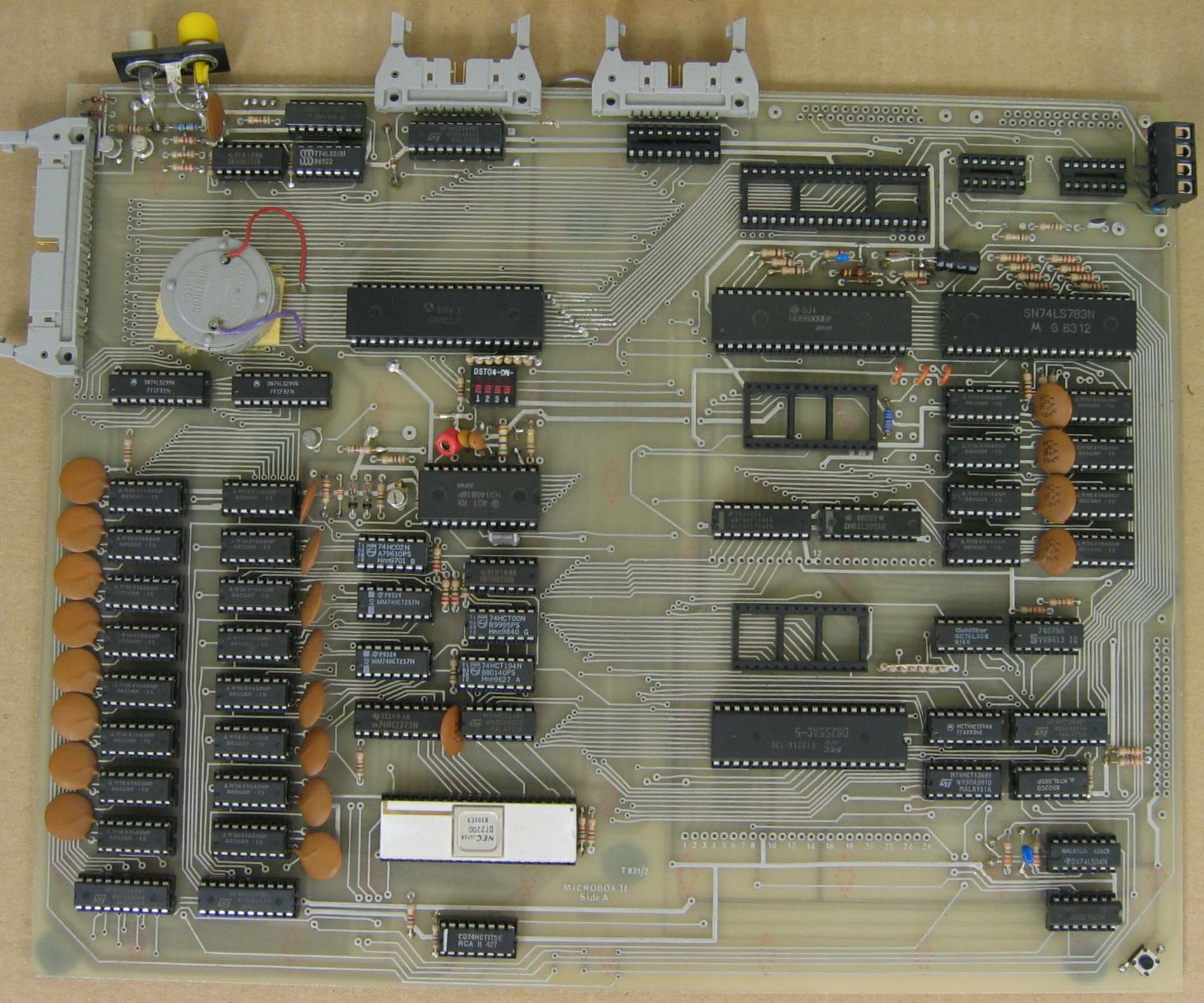
The three jumpers between the 6809 and the SAM can configure the SAM to run from a 14.31818 or 16 MHz crystal as shown on page 12 of the datasheet. Standard configuration is to run it from an external 16 MHz clock from the 74LS00 in the bottom right-hand corner (IC14D).
Someone asked why the 8255 is barse-ackwards. No, I don't know either. Whoever built this thing put the socket in the wrong way around.
The one strange thing about the Microbox is that the designer (Dave Rumball / Micro Concepts) did not place mounting holes anywhere on the PCB, so there's no easy way to bolt the PCB to a case. The shape of the PCB also doesn't fit into a modern PC case (the obvious choice, I think) but it does go into an old "AT" style case (the one with the runners for the floppies). The PCB is about 300mm x 240mm (12" x 9").
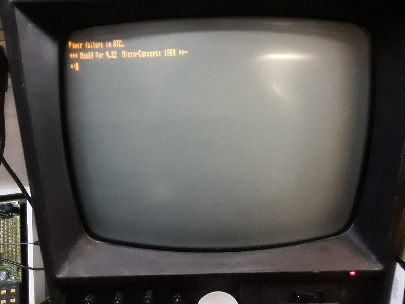
It works!
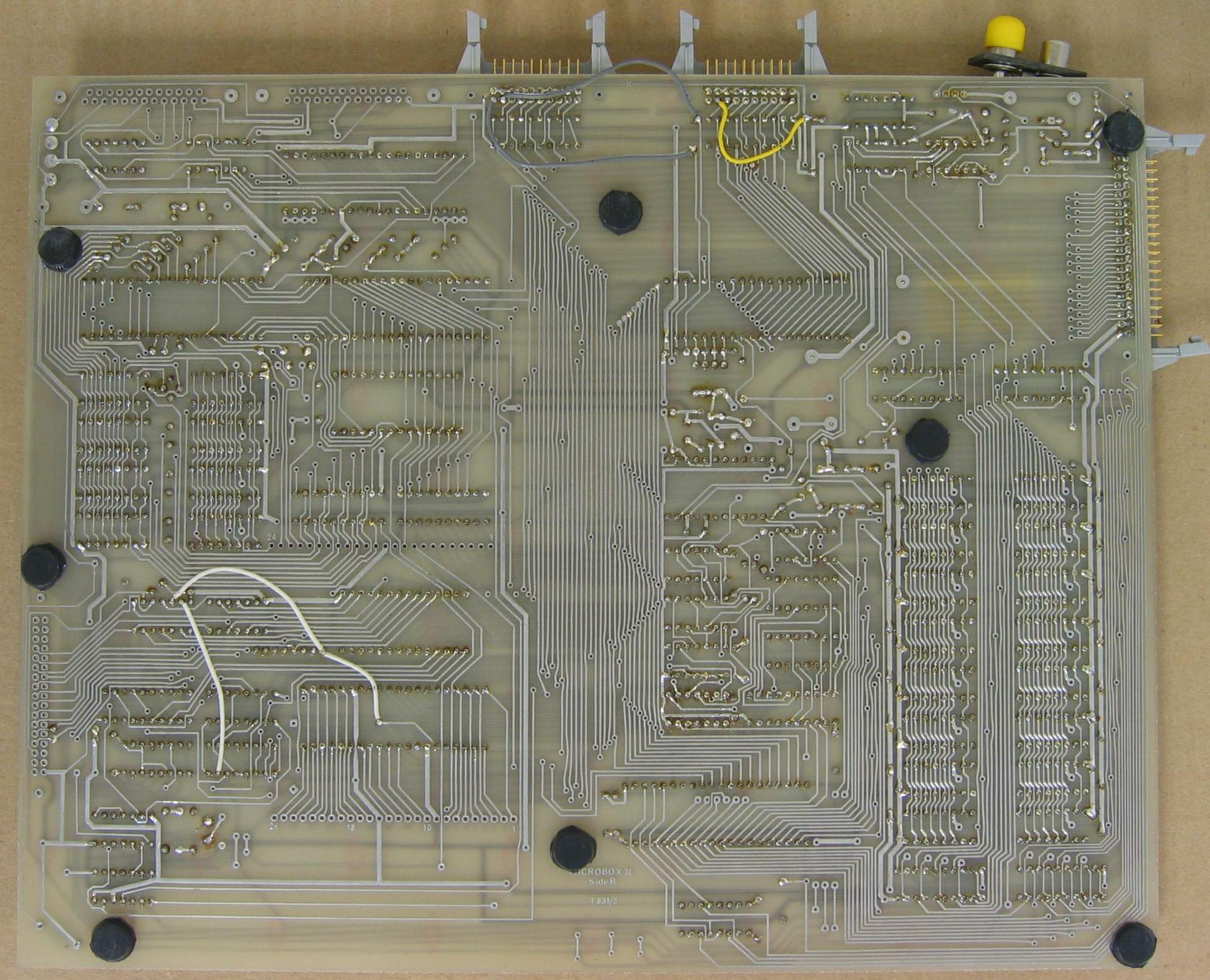
The innovation jumpers visible on the back of the "as received" picture above are documented in the User Notes:
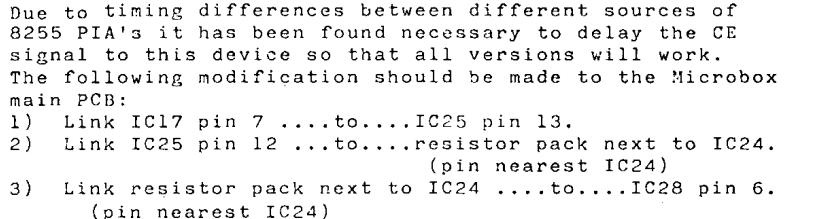
IC17: 74LS138, pin 7 = /PIA2 (ETI Fig 2) AKA /DISC (ETI Fig 6). Connects to 8255 /CS via R37, which
is not fitted for this mod.
IC25: 7407, pins 13 and 12 is an unused buffer (being open collector, it needs a pull-up resistor
on the output.
IC28: 8255, pin 6 = /CS.
Items 1 and 2 move /CA1 from printer connector pin 1 inner / 2 to keyboard connector pin 9 inner / 17.
Item 3 connects the printer BUSY to bit 7 of the keyboard port -- unused with a 7-bit keyboard.
Item 4 connects printer /STROBE (output) to the connector.
Items 1,2 and 4 bring the PCB in line with the ETI Fig 3 schematic. I did not implement Item 3 on my PCB.
I chose to do things a little differently, so here is a summary of the modifications I performed.
Because I am now using IC25 to open-collector buffer the side-select signal for double-sided floppy support, my 8255 is currently not working.
Back in the good old days, there was a little shop called the Electronics Supermarket just around the corner from the Greenmarket Square. They sold all kinds of nifty stuph I couldn't afford, I remember they had an AIM 65 on display.
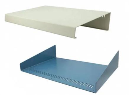
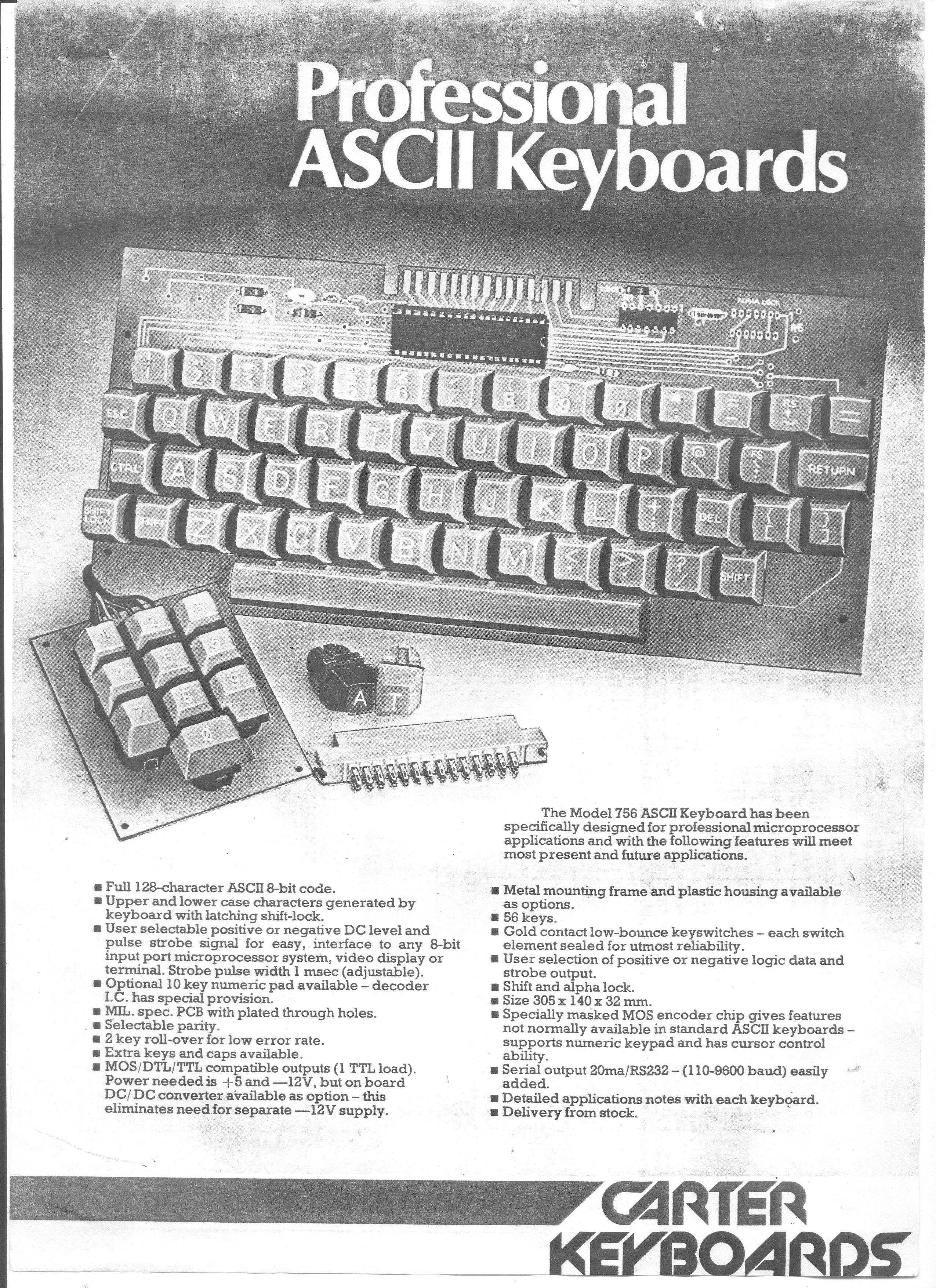
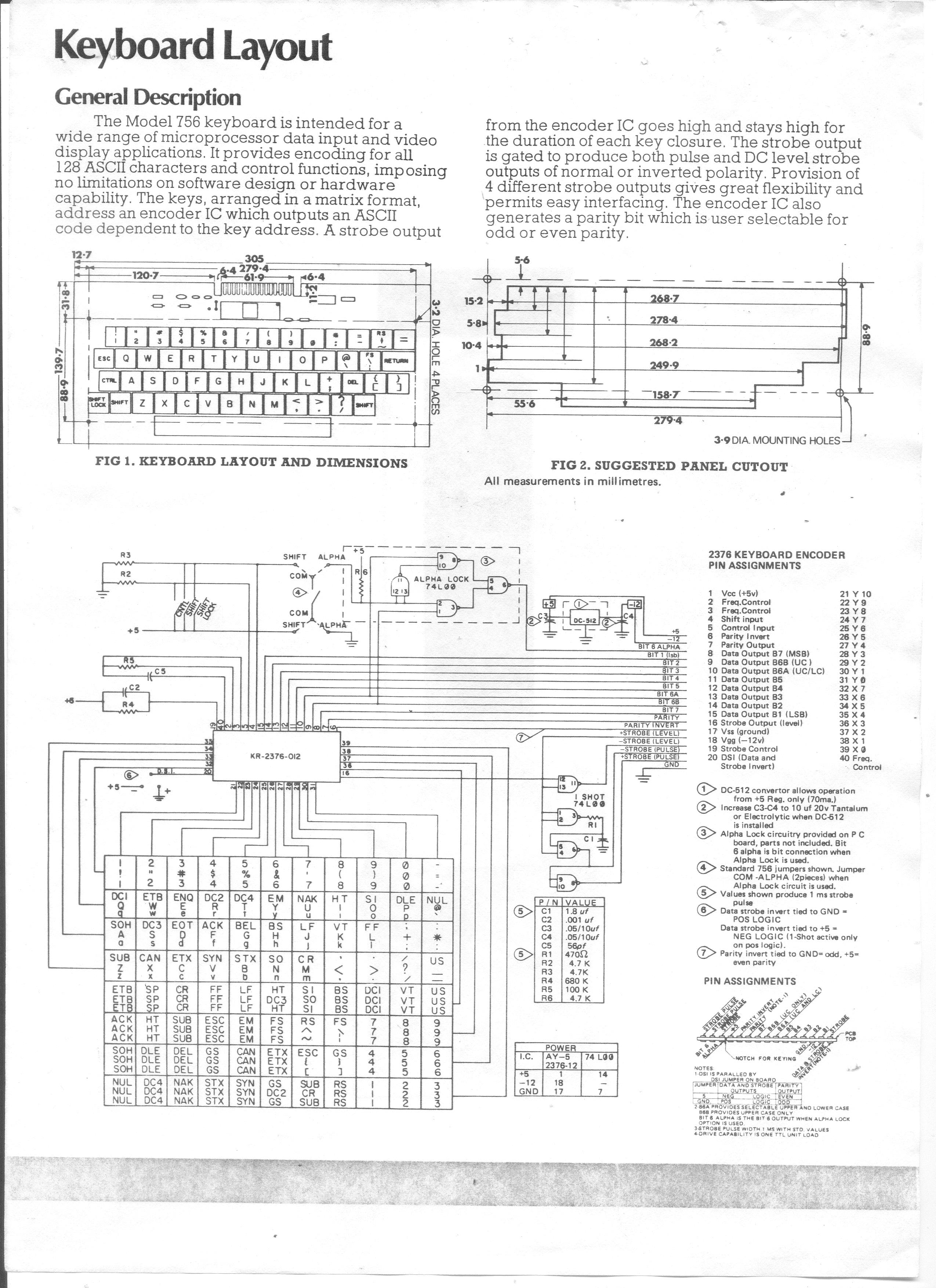
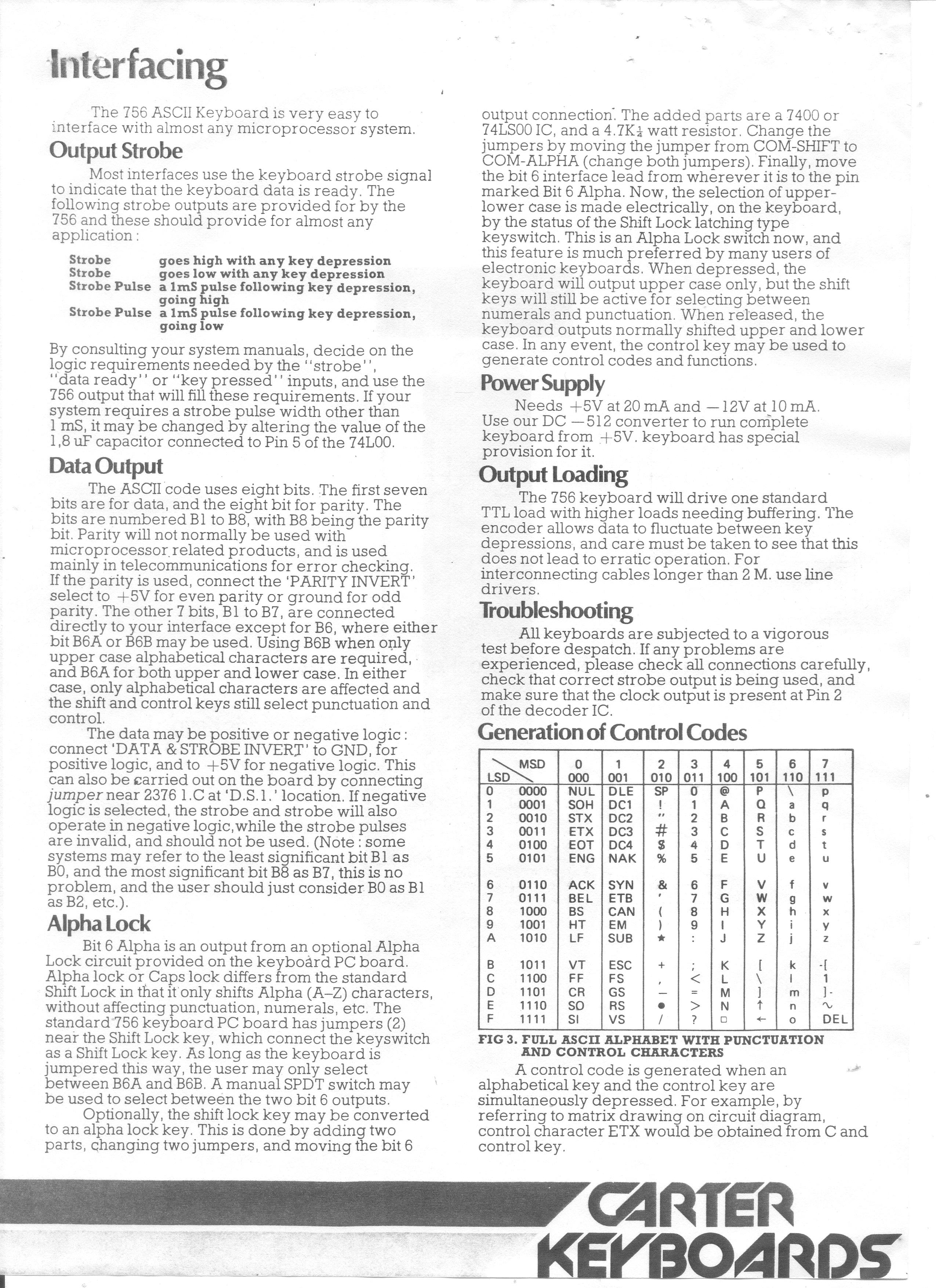
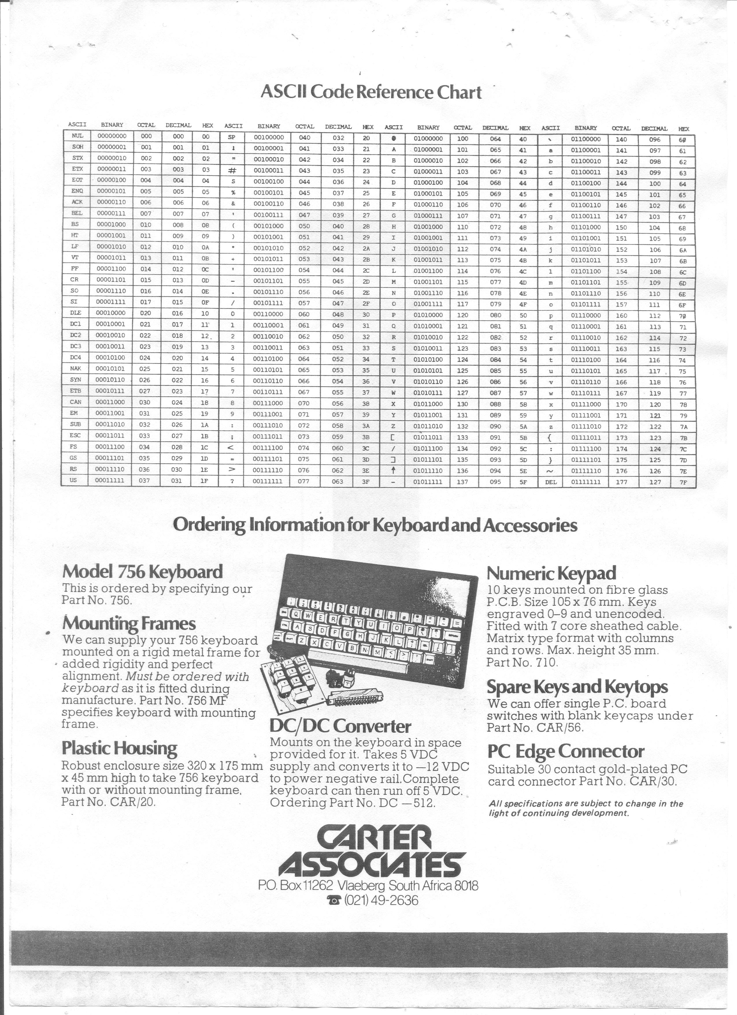
Anyway, I bought an ASCII keyboard from them, model 756C. It's made by Carter Keyboards, here are the docs I got with it Page 1, 2, 3 and 4. This is functionally identical to the George Risk Industries datasheet I pulled off the web. I suspect they (GRI) just rubbed the badging off a bit and flogged the thing as their own.
These keyboards (well, the KR2376 encoder chip) need -12V in addition to the +5V supply and they do have a site for a DC/DC converter. I removed an ethernet DC/DC converter and hacked it onto that site, it wasn't pin-compatible. The Microbox provides -12V on the keyboard connector, I suspect the 756 or keyboards based on the same chip was pretty much standard all over the world for a decade at least.
Note that the keyboard matrix is shown in the documentation is not correct for the KR-2376-150 that I have on my 756 keyboard.
Sebastian Kienzl's interface does all the hard work in a PIC. Or you can do it the hard way.
|
After much deliberation I decided to build my Microbox II into a
Hammond Sloped Front Desktop Enclosure,
RS
Components 868-5312. At 431 x 280 x 89mm, the
Microbox PCB fits very nicely, with room for a small power supply
and of course the 756 keyboard.
|
|
Starting with the MON09 V4.5 sources from the FLEX library disk, I modified things to work with as09 under DOS (DOSBox). The resulting binary is identical to the one on the library disk.
Alternatively you can use FLEXemu and ASEMB on the original disk image (which you will need to pipe through FloppyMaint to get FLEXemu to read it). It's slower than as09 though. Also take note that this creates a FLEX binary which is not binary, it consists of "0x02 address length data" records.
There's also LWTOOLS which is much faster under windows, but the binary it creates differs from the as09 / ASEMB binary. Specifically:
A7 A4  STA  0,Y (as09 / ASEMB)
A7 20  STA  0,Y (LWTOOLS)
These are equivalent, the former is no offset, Y register direct and the latter is 5-bit offset, Y register direct, offset = 0.
Caveat: if you try to get LWTOOLS to emit a binary you get the bytes in source file order, i.e. the stuff that's supposed to go at $F000 will be at the start of your binary and the $E000 stuff will be in the middle. Make it spit out S-Records and convert that to a binary.
I should maybe also mention asm6809, I tried it but it expects a different input file format. All comments need a ; for example. I think it can be made to work with a bit of effort.
I needed a way to get my code transferred to the Microbox. Because of the way MON09 works, in that it reads two characters, parses them and passes control to the code to handle that command (as opposed to for example MVME101BUG, which takes a two character command + CR) I could add a command "S1" which then reads the rest of the S-Record line and stores it in memory.
In what used to be COMTABLE:
; WRM 2022-01-15 Add S1
          FCC 'S1'
          FDB S1 ; At end of $E000-$EFFF block
and after "SB":
S1        JSR BYTE             ; Get one byte in A (S Record length) (preserves B)
          DECA                 ; Payload is three bytes less than record length
          DECA                 ; because of the address
          DECA                 ; and checksum
          PSHS A
          JSR BADDR            ; Get two byte destination address in X (Destroys A and B)
          PULS B               ; Count now in B
S1LOOP    JSR BYTE             ; Get byte (preserves B)
          STA ,X+              ; store it
          DECB
          BNE S1LOOP
          JSR BYTE             ; Get checksum (and ignore)
          JMP CONTRL
So with a PC emulating a terminal for I/O, I can paste an S-Record file and it ends up in memory at the right place. The terminal emulator does need to support throttling.
I should probably add S9 to just swallow everything up to the end of the line, rather than live with the error I get at the moment.
This being the 21st century, I decided to go with a single 3 1/2" floppy. And that's just because I want to, it's easier to use a GoTek.
Now modern 3 1/2" floppy drives support HD, i.e. 1.44 Meg disks. These run at twice the clock rate (using FM, the data rate is half the clock rate, using MFM they're the same). So you can do 125kbps FM (clock is 250kHz) or 250kbps MFM (clock is still 250kHz) using DD disks (no hole) and 250kbps FM or 500kbps MFM (clock is 500kHz) using HD disks (with the hole opposite the write protect hole). The hole tells the drive what the data rate is (The 5 1/4" world is much less simple. You need to tell the drive what kind of disk to expect, and the disk runs at 300rpm for SD/DD and at 360rpm for HD. OR at 360rpm all the time but then you need to feed data to it at 300kbps in DD mode).
Anyway, the 6809 can't do 500kbps, and the 1770 can't do 500kHz, so my options are SD 125kbps FM or DD 250kbps MFM. And since interoperability is completely moot, I'm sticking to DD only. (I am not going to bother with single-density. There might be someone out there using 3 1/2" disks in single-density mode, sucks to be them). So I need to update the MON-09 built-in, 40-track, single-density format routine to 80 track double-density.
The standard 300rpm and 250kbps gives you (60/300) * 250 = 50 kilobits = 6250 bytes per track (a track is one side, a cylinder is both sides) in MFM mode (SD would give 3125 bytes per track). These are raw bytes, they get wrapped in track and sector headers and footers and you get to use what's left.
Page 17 of the WD1770 datasheet shows what it expects a track to look like. But one would want compatibility with other FDCs as well. So I decided to reverse-engineer some existing code. This proved to be a bit of a mistake. The code claims to do one thing and then end up doing another, leading to confusion on my part. Either the authors had an unintentional bug which just so happened to make things work, or they were lazy and left dead-end code, well-commented dead-end code, in there to confuse people like me. The code builds a sector header and then overwrites most of it with the first track header. The WD1770 doesn't need a sector header but the code is there, leading me to think that the header is needed for other controllers maybe, except as mentioned it then gets overwritten anyway.
I've documented what the double sided newdisk utility for the Microbox (NEWDISK2.TXT from library disk 49 does if you look at the code quickly, as well as what it actually does.
Single Density

   WD1770 Datasheet   |       NEWDISK2       |       NEWDISK2       |        MON09         |
        Format        |     What it says     |     What it does     |                      |
  No. of   Hex value  |  No. of   Hex value  |  No. of   Hex value  |  No. of   Hex value  |
  bytes    to write   |  bytes    to write   |  bytes    to write   |  bytes    to write   |  Info
----------------------+----------------------+----------------------+----------------------+--------------------------------
    40        FF      |    30        FF      |                      |                      | Post index Gap       (Gaps 1+2)
                      |     6        00      |                      |     6        00      | Pll lock-up
                      |     1        FC      |                      |     1        FC      | Index address mark
                      |                      |                      |     7        FF      | MON09-specific gap
 /   6        00      | /   6        00      | /   6        00      | /   6        00      | Pll lock-up
 |   1        FE      | |   1        FE      | |   1        FE      | |   1        FE      | ID address mark
 |   1                | |   1                | |   1                | |   1                | Track number
 |   1                | |   1        00      | |   1        00      | |   1        00      | Side number
 |   1                | |   1                | |   1                | |   1                | Sector number
 |   1                | |   1        01      | |   1        01      | |   1        01      | Sector length
 |   1        F7      | |   1        F7      | |   1        F7      | |   1        F7      | Writes 2 CRC bytes
 |  11        FF      | |  11        FF      | |  11        FF      | |  11        FF      | Sector ID / Data Gap (Gap 3a)
 |   6        00      | |   6        00      | |   6        00      | |   6        00      | Pll lock-up          (Gap 3b)
 |   1        FB      | |   1        FB      | |   1        FB      | |   1        FB      | Data address mark
 |                    | |   2        xx      | |   2        xx      | |   2        xx      | Track/Sector link (FLEX)
 |   128/256/512/...  | | 254        FE      | | 254        FE      | | 254        00      | Data
 |   1        F7      | |   1        F7      | |   1        F7      | |   1        F7      | Writes 2 CRC bytes
 \  10        FF      | \  12        FF      | \  12        FF      | \  14        FF      | Post data Gap        (Gap 4)
   369 approx FF      |              FF      |              FF      |   256        FF      | Runout Gap. Write until
                      |                      |                      |                      | next index hole.
  40 + n(31+data+12)  |  37 + 10*(31+256+14) |  10*(31+256+14)      |  14+10*(31+256+16)   | Bytes per track
                      |  3047                |  3010                |  3044                | With 10 x 256 byte sectors
                      |  78                  |  115                 |  81                  | Bytes slack

Double Density

   WD1770 Datasheet   |       NEWDISK2       |       NEWDISK2       |
        Format        |     What it says     |     What it does     |
  No. of   Hex value  |  No. of   Hex value  |  No. of   Hex value  |
  bytes    to write   |  bytes    to write   |  bytes    to write   |  Info
----------------------+----------------------+----------------------+--------------------------------
    60        4E      |    60        4E      |                      | Post-index Gap      (Gaps 1+2)
                      |    12        00      |                      | Pll lock-up
                      |     3        F6      |                      | 3 synchronisation bytes
                      |     1        FC      |                      | Index address mark
 /  12        00      | /  12        00      | /  12        00      | Pll lock-up
 |   3        F5      | |   3        F5      | |   3        F5      | 3 synchronisation bytes
 |   1        FE      | |   1        FE      | |   1        FE      | ID address mark
 |   1                | |   1                | |   1                | Track number
 |   1                | |   1                | |   1                | Side number
 |   1                | |   1                | |   1                | Sector number
 |   1                | |   1        01      | |   1        01      | Sector length
 |   1        F7      | |   1        F7      | |   1        F7      | Writes 2 CRC bytes
 |  22        4E      | |  22        4E      | |  22        4E      | Sector ID / Data Gap  (Gap 3a)
 |  12        00      | |  12        00      | |  12        00      | /Write splice time    (Gap 3b)
 |                    | |                    | |                    | \Pll lock-up time
 |   3        F5      | |   3        F5      | |   3        F5      | 3 synchronisation bytes
 |   1        FB      | |   1        FB      | |   1        FB      | Data address mark
 |                    | |   2        xx      | |   2        xx      | Track/Sector link (FLEX)
 |   n                | | 254        FE      | | 254        FE      | Data
 |   1        F7      | |   1        F7      | |   1        F7      | Writes 2 CRC bytes
 \  24        4E      | \  24        4E      | \  24        4E      | Post Data Gap          (Gap 4)
   668 approx 4E      |              4E      |              4E      | Runout Gap. Write until
                      |                      |                      | next index hole.
  70 + n(60+data+26)  |  76 + 18*(60+256+26) |  18*(60+256+26)      | Bytes per track
                      |  6232                |  6156                | With 18 x 256 byte sectors
                      |  18                  |  94                  | Bytes slack
The 18 bytes slack in what NEWDISK2 seemed to do in DD mode is what then started me investigating. Two FUFU list members sent me NEWDISK5 and NEWDISK3 and from that I finally twigged. The codebase exists to be used with 8", 5 1/4" and other disk formats. You just tweak the defines at the beginning of the code, the code then clears the workspace, sets up a track header, and based on your defines overwrites the track header again. When they ported newdisk to the Microbox, they removed the now-redundant comments but not the now-redundant code.
Another funny I noticed is that the side is set to 0 for both sides of SD disks. The reason for this is
That's what I would call an SWTPC "quirk". On the DC-4 controller the 1797 side select output is connected via an inverter to the DDEN pin. So commands with side=0 select single density and those with side=1 select double density. Since you cannot stop a 1797 from checking for the correct side, the side bytes in the sector address fields must be 0 on both sides for single density and 1 on both sides for double density. On the DC-4 the floppy disk side is selected by one of the bits in the drive select register.
Yea, OK, again, interoperability = moot, so bugger that.
OK, so now I feel I know enough to write my own newdisk.
Finding 1: You need a post-index gap. Trying to emulate what NEWDISK2 does did not work for me (in DD, didn't test SD). I added the 60 x 4E (but not the 00 F6 FC sequence) and that seems to work.
Finding 2: NEWDISK2 writes the buffer out, testing for DRQ but not for BUSY. If the drive rotates too fast, BUSY will drop, DRQ won't happen, and the system hangs. MON09 tests for BUSY, but in DD mode this only works at high (2MHz) speed.
Write loop from NEWDISK2. This works at 1MHz, double-density.

        LDB     #2
        LDX     #WORK
L0583   BITB    <WD1770COM
        BEQ     L0583       ; S1 = DRQ = 0
        LDA     ,X+
        STA     <WD1770DAT
        CMPX    TEMP1       ; End of buffer
        BNE     L0583

Write loop from MON09. This works at 2MHz, double-density, but fails at 1MHz.

        LDX     #WORK
L0583   LDA     <WD1770COM
        BITA    #$01       ; S0 = BUSY
        BEQ     L0590      ; BUSY = 0, exit
        BITA    #$02       ; S1 = DRQ
        BEQ     L0583      ; DRQ = 0, loop
        LDA     ,X+
        STA     <WD1770DAT
        CMPX    TEMP1
        BNE     L0583
L0590 ...
The FLEX User Group has a bunch of utilities to move data between physical disks, DSK images, and the Windows / Linux world.
I use Michael Evenson's FloppyMaint (v1.09 of 2005, works for me).
There is also an emulator, Wolfgang Schwotzer's FlexEmu. It comes with FLEXplorer, another way to handle DSK images.
FLEX supported effectively unlimited (for the time) size disks - 256 tracks with 255 sectors of 256 bytes each, for just under 16 megabytes -- FLEX was released in 1976 while Shugart only introduced the 5 megabyte ST-506 in 1980. But here's the rub. FLEX does not support subdirectories. It wasn't a thing back then. And having a single 16 megabyte disk with a couple thousand files on it... doesn't work. It might be better to support maybe 64 smaller disks. UniFLEX sounds good but it needs 128k RAM and maybe DMA capable disk drives, and that won't fly on this hardware.
This (still) being the 21st century, my printer is hanging off CAT5 on the other side of the house. So I can use what used to be the printer port to interface to a "20481 / HD44780" type 4x20 LCD in 4-wire mode, and maybe hang a few LEDs off the remaining pins.
Over the years Dave Dunfield wrote stacks of good code and released a substantial amount of it into the public domain. His Runtime Aid for Interactive Debugging can be found as part of the N8VEM CUBIX release.
I removed the command-line code at the beginning and changed GETCHR, RDCON and WRCON to use MON-09 calls.
Raid> D C052,C071
C052 17 03 4E       ..N   LBSR  $C3A3
C055 52             R     FCB
C056 61             a     FCB
C057 69 64          id    ROL   $04,S
C059 3E             >     FCB
C05A 20 00           .    BRA   $C05C
C05C 17 03 5B       ..[   LBSR  $C3BA
C05F 17 03 67       ..g   LBSR  $C3C9
C062 8E C0 7B       ..{   LDX   #$C07B
C065 A1 80          ..    CMPA  ,X+
C067 27 0E          '.    BEQ   $C077
C069 30 02          0.    LEAX  $02,X
C06B 6D 84          m.    TST   ,X
C06D 26 F6          &.    BNE   $C065
C06F 17 03 31       ..1   LBSR  $C3A3
Raid>
Nice! A mini-disassembler like my Apple ][ has.
| 876 hits since 2020-10-06. | Back to Wouter's Microbox II Page | (This page last modified 2025-07-10) |
