Wouter's Apple Macintosh : Mac Plus PALs
Back in 2011 when I started this page, nobody had completely reverse-engineered and
documented the PALs.
We had
but that was not complete.
(See also this thread).
I removed the PALs from my Mac Plus, fitted sockets, and started reading and reverse
engineering, but then other stuff happened, and I never got anywhere.
Fast forward to 2025 and
turns out other people were more dedicated
than I tend to be. So that takes care of that.
~~~For (my own) Reference~~~
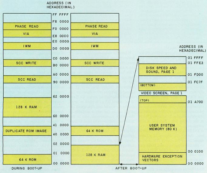
Here's the memory map of the very first (128k) Macintosh, Byte, February 1984.
And some fascinating reading, the
Macintosh Hardware Memory Map by Burrell Smith and Brian Howard, dated 13 April 1983. It notes that the addresses used by the
software and documentation is at the upper end of the memory block allocated for the device (all the address lines are not decoded,
so any device appears multiple times in the address space) to save "a small amount of power".
The 128k and 512k Macs have BMU0 and BMU1 PALs, with BMU0 being a registered PAL
responsible for wait states etc. In the Mac Plus this becomes BMU1 (with the same
pinout / pin assignment as the 128k Mac) and BMU2. The Mac Plus also adds a CAS PAL
which controls the four SIMMs.
BMU1 : Bus Management Unit 1 : 16L8
| /AS | I | 11 | | 10 | | GND |
| /IWM | O | 12 | | 9 | I | A21 |
| /SCCRD | O | 13 | | 8 | I | A22 |
| /SCCEN | O | 14 | | 7 | I | A23 |
| /VPA | O | 15 | | 6 | I | OVERLAY |
| /ROM | O | 16 | | 5 | I | L13 |
| /RAM | O | 17 | | 4 | I | /VCA |
| VC0 | O | 18 | | 3 | I | VA6 |
| VC1 | O | 19 | | 2 | I | VA7 |
| Vcc | | 20 | | 1 | I | VA8 |
OVERLAY is a signal from PA4 on the 6522. It's used to map the ROM to address zero after reset,
once the code starts executing it jumps to $40 0000 (128k Mac) and then RAM is mapped into 0.
L13 comes from the video circuitry, as does VA6..VA8.
/VCA comes from BMU2 (BMU0 on the 128k Mac).
From Jecel's notes (for the 128k / 512k Mac):
/IWM   :=  A23 *  A22 * /A21 * /AS             ; 0xC0 0000 - 0xDF FFFF (0xDF E1FF)
/SCCRD :=  A23 * /A22 * /A21 * /AS             ; 0x80 0000 - 0x9F FFFF (0x9F FFF8)
/SCCEN :=  A23 * /A22 * /AS                    ; 0x80 0000 - 0xBF FFFF (0x9F FFF8 - RD, 0xBF FFF9 - WR)
/VPA   :=  A23 *  A22 *  A21 * /AS             ; Synchronous I/O (6800 style) 0xE0 0000 - 0xFF FFFF
/ROM   := /A23 *  A22 * /A21 * /AS             ; 0x40 0000 - 0x5F FFFF
        + /A23 * /A22 * /A21 * /AS * OVERLAY   ; 0x00 0000 - 0x1F FFFF when OVERLAY enabled
        +  A23 * /A22 * /AS                    ; 0x80 0000 - 0xBF FFFF
        +  A23 * /A21 * /AS                    ; 0x80 0000 - 0x9F FFFF and 0xC0 0000 - 0xDF FFFF
/RAM   := /A23 * /A22 * /A21 * /AS * /OVERLAY  ; 0x00 0000 - 0x1F FFFF
        + /A23 *  A22 *  A21 * /AS * OVERLAY   ; 0x60 0000 - 0x7F FFFF when OVERLAY is enabled
VC0    :=
VC1    :=
I reverse engineered the BMU1 using my Expro 80 EPROM programmer and
the source code to ALL03, modified
to apply the 1024 possible combinations to the input pins of a 16L8 and to read the one byte output.
This gave me
/IWM   = /AS * A23 * A22 * /A21         ; 110x   0xC0 0000 - 0xDF FFFF (0xDF E1FF)
/SCCRD = /AS * A23 * /A22 * /A21        ; 100x   0x80 0000 - 0x9F FFFF (0x9F FFF8)
/SCCEN = /AS * A23 * /A22               ; 10xx   0x80 0000 - 0xBF FFFF (0x9F FFF8 - RD, 0xBF FFF9 - WR)
/VPA   = /AS * A23 * A22 * A21          ; 111x   Synchronous I/O (6800 style) 0xE0 0000 - 0xFF FFFF
/ROM   = /A23 * A22 * OVERLAY +         ; 01xx   0x40 0000 - 0x7F FFFF when OVERLAY = 0 AND
         /A22 * OVERLAY +               ; x0xx   0x00 0000 - 0x3F FFFF and 0x80 0000 - 0xBF FFFF when OVERLAY = 1 AND
         A23 * /A22 +                   ; 10xx   0x80 0000 - 0xBF FFFF AND
         A22 * /A21                     ; x10x   0x40 0000 - 0x5F FFFF and 0xC0 0000 - 0xDF FFFF
/RAM   = /A23 * A22 * A21 * OVERLAY +   ; 011x   0x60 0000 - 0x7F FFFF when OVERLAY=1 AND
         /A22 * /OVERLAY +              ; x0xx   0x00 0000 - 0x03 FFFF and 0x80 0000 - 0x9F FFFF when OVERLAY = 0
         A23 * /A22                     ; 10xx   0x80 0000 - 0xBF FFFF

VC0 = /VCA * L13 * VA6 +
      /VCA * /L13 * VA7 * /VA8
VC1 = /VCA * L13 * VA6 +
      /VCA * /L13 * /VA7 * VA8
Fast forward to 2025 and I ran
Porchy's brute-forced GAL JED file
through Opal's JED2EQN and got essentially the same, except that the /ROM signal is defined as where the ROM
isn't rather than where the ROM is.
; The ROM mapping is negative logic - these equations determine when the ROM
; is _disabled_
ROM = A23 * A22 * A21                ; 0xE00000-0xFFFFFF
      + /OVERLAY * /A23 * /A22       ; 0x000000-0x3FFFFF
      + OVERLAY * A22 * A21          ; 0x600000-0x7FFFFF and 0xE00000-0xFFFFFF
; With OVERLAY=0, /ROM is low for 0x400000-0xDFFFFF
; With OVERLAY=1, /ROM is low for 0x000000-0x5FFFFF and 0x800000-0xDFFFFF
Analysis
- The first six outputs are a function of the first five inputs (i.e. /IWM, /SCCRD, /SCCEN,
/VPA, /ROM and /RAM depend on /AS, A21..A23 and OVERLAY). This matches Jecel.
- The last two outputs are functions of the other five inputs (i.e. VC0 and VC1 depend on
L13, /VCA and VA6..VA8)
- /IWM is asserted (=0) from 0xC0 0000 to 0xDF FFFF (same as 128k Mac)
- /SCCRD is asserted from 0x80 0000 to 0x9F FFFF (same as 128k Mac)
- /SCCEN is asserted from 0x80 0000 to 0xBF FFFF (same as 128k Mac)
- /VPA is asserted from 0xE0 0000 to 0xFF FFFF (same as 128k Mac)
- /ROM is always asserted from 0x40 0000 to 0x5F FFFF and 0x80 0000 to 0xDF FFFF
- With OVERLAY = 0, /ROM is asserted from 0x40 0000 to 0x7F FFFF
- With OVERLAY = 1, /ROM is asserted from 0x00 0000 to 0x5F FFFF
- /RAM is always asserted from 0x80 0000 to 0xBF FFFF)
- With OVERLAY = 0, /RAM is asserted from 0x00 0000 to 0x3F FFFF
- With OVERLAY = 1, /RAM is asserted from 0x60 0000 to 0x7F FFFF
This means that /ROM and /RAM clash at 0x80 0000 to 0xBF FFFF. This is consistent with the original
512K memory map. However, on the Plus, /ROM and /RAM are not the actual chip selects,
some further logic happens in the TSM. As a matter of fact, /ROMCE comes from the CAS, which
doesn't even use /ROM as an input. /ROM goes to the BMU2 and TSM. Go figure. (They probably just
kept the 512 K BMU on the basis of "if it ain't broke").
CAS : 20L8
| TSEN2 | I | 13 | | 12 | | GND |
| RAMSIZE | I | 14 | | 11 | I | ROWS |
| /ROMCE | O | 15 | | 10 | I | /CASH |
| OVERLAY | I | 16 | | 9 | I | /CASL |
| /CAS0L | O | 17 | | 8 | I | VID/u* |
| /CAS0H | O | 18 | | 7 | I | C2M |
| /CAS1L | O | 19 | | 6 | I | A23 |
| /CAS1H | O | 20 | | 5 | I | A22 |
| /SCSI | O | 21 | | 4 | I | A21 |
| /DACK | O | 22 | | 3 | I | A20 |
| /AS | I | 23 | | 2 | I | A19 |
| Vcc | | 24 | | 1 | I | A9 |
The CAS, TSG and ASG share TSEN2, which is pulled low via R36, a 150 ohm resistor.
This signal does not seem to go anywhere else. I included it in the analysis
anyway, which of course doubled the size of the raw data file.
RAMSIZE and ROWS come from two jumpers, R8 and R9. When using 4 x 256K SIMMS for 1 Mbyte these both need to be
present. When fitting 4 x 1M SIMMS for 4 Mbyte RAM, you need to
snip R8 or
R8 and R9.
/ROMCE is the ROM /CE line (/ROM is something else). On the Plus, A17 is connected to the ROM
/OE so take that into consideration when computing memory maps.
/SCSI and /DACK go to the 5380 SCSI controller.
/CASL and /CASH are from the TSM, and /CAS0L|H|1L|H are the CAS signals for the four SIMMs.
Now we're dealing with more inputs, and fewer outputs. This is where Minilog shat the bed:
[...]
00011111010000 | 1000000
CAN'T HANDLE MORE THAN 2000 INPUT TERMS
Espresso worked, and this is as far as I got. Never mind, as mentioned the JED files for all
the PALs are now available, and since I want to understand how things work, I ran them all through
JED2EQN.
/ROMCE = /A23 * A22 * /A21 * /A20 +     ; 0100  0x400000-0x4FFFFF
         /A23 * /A21 * /A20 * OVERLAY   ; 0x00  0x000000-0x0FFFFF as well as 0x400000-0x4FFFFF when OVERLAY=1
ROMCE.oe = TSEN2

/CAS0L = /CAS0L * /CASL
    + /C2M * /CASL * /ROWS
    + /A21 * /C2M * /VID * /CASL * RAMSIZE * ROWS
    + /A19 * /C2M * /VID * /CASL * /RAMSIZE * ROWS
CAS0L.oe = TSEN2
/CAS0H = /CAS0H * /CASH
    + /C2M * /CASH * /ROWS
    + /A21 * /C2M * /VID * /CASH * RAMSIZE * ROWS
    + /A19 * /C2M * /VID * /CASH * /RAMSIZE * ROWS
CAS0H.oe = TSEN2
/CAS1L = /CAS1L * /CASL
    + /C2M * VID * /CASL * ROWS
    + A21 * /C2M * /VID * /CASL * RAMSIZE * ROWS
    + A19 * /C2M * /VID * /CASL * /RAMSIZE * ROWS
CAS1L.oe = TSEN2
/CAS1H = /CAS1H * /CASH
    + /C2M * VID * /CASH * ROWS
    + A21 * /C2M * /VID * /CASH * RAMSIZE * ROWS
    + A19 * /C2M * /VID * /CASH * /RAMSIZE * ROWS
CAS1H.oe = TSEN2

/SCSI = /AS * /A23 * A22 * /A21 * A20 * A19 * /A9 ; 0101 1xxx xxxx xx0x xxxx xxxx 0xA80000-0xAFFFFF with A9=0
SCSI.oe = TSEN2
/DACK = /AS * /A23 * A22 * /A21 * A20 * A19 * A9  ; 0101 1xxx xxxx xx1x xxxx xxxx 0xA80000-0xAFFFFF with A9=1
DACK.oe = TSEN2

/OVERLAY = gnd
OVERLAY.oe = gnd
Analysis
/ROMCE is good for 1 MByte of ROM, mapped at 0x000000 at startup and at 0x400000 to execute.
The MAC Plus has four SIMM sockets, in two rows (each SIMM is 8 bits wide). Each socket has its
own CAS line. If only two SIMMS are fitted, R9 "ONE ROW" should be installed,
which pulls ROWS = 0. For four SIMMS, R9 is removed and ROWS = 1.
The MAC Plus shipped with 1 Mbyte of RAM (4 x 256k SIMMs) and can be upgraded to a maximum of
4Mbyte RAM (4 x 1Mbyte SIMMs).
512k:  2 x 256kbyte SIMMs
1MB:   4 x 256kbyte SIMMs
2MB:   2 x 1Mbyte SIMMs
2.5MB: 2 x 256kbyte + 2 x 1Mbyte SIMMs
4MB:   4 x 1Mbyte SIMMs
If all SIMMS are 256k, R8 "256K RAMs only" should be installed, which pulls RAMSIZE = 0.
With 1Mbyte SIMMS R8 is removed and RAMSIZE = 1.
With ROWS = 0 and RAMSIZE = 0

/CAS0L = /CAS0L * /CASL
    + /C2M * /CASL

/CAS0H = /CAS0H * /CASH
    + /C2M * /CASH

/CAS1L = /CAS1L * /CASL ; unused

/CAS1H = /CAS1H * /CASH ; unused

With ROWS = 0 and RAMSIZE = 1

/CAS0L = /CAS0L * /CASL
    + /C2M * /CASL

/CAS0H = /CAS0H * /CASH
    + /C2M * /CASH

/CAS1L = /CAS1L * /CASL ; unused

/CAS1H = /CAS1H * /CASH ; unused

With ROWS = 1 and RAMSIZE = 0

/CAS0L = /CAS0L * /CASL
    + /C2M * /CASL
    + /A19 * /C2M * /VID * /CASL

/CAS0H = /CAS0H * /CASH
    + /C2M * /CASH
    + /A19 * /C2M * /VID * /CASH

/CAS1L = /CAS1L * /CASL
    + /C2M * VID * /CASL
    + A19 * /C2M * /VID * /CASL

/CAS1H = /CAS1H * /CASH
    + /C2M * VID * /CASH
    + A19 * /C2M * /VID * /CASH

With ROWS = 1 and RAMSIZE = 1

/CAS0L = /CAS0L * /CASL
    + /A21 * /C2M * /VID * /CASL

/CAS0H = /CAS0H * /CASH
    + /A21 * /C2M * /VID * /CASH

/CAS1L = /CAS1L * /CASL
    + /C2M * VID * /CASL
    + A21 * /C2M * /VID * /CASL

/CAS1H = /CAS1H * /CASH
    + /C2M * VID * /CASH
    + A21 * /C2M * /VID * /CASH
- /ROMCE is the "real" ROM select which matches the memory map.
- /CASxL and /CASxH reduces to four less complex sets of equations depending on the jumper settings
- /SCSI is asserted for 0xA8 xxxx to 0xAF xxxx as long as A9 is high
- /DACK is asserted for 0xA8 xxxx to 0xAF xxxx as long as A9 is low.
I still have a lot to learn here.
BMU2 : Bus Management Unit 2 : 20R4
| /TSEN0 | /OE | 13 | | 12 | | GND |
| /TSEN0 | I | 14 | | 11 | I | /DMA |
| RA8 | O | 15 | | 10 | I | C2M |
| /245OE | O | 16 | | 9 | I | R/W |
| VA13 | R | 17 | | 8 | I | L13 |
| VA12 | R | 18 | | 7 | I | L12 |
| /VCA | R | 19 | | 6 | I | VA11 |
| /VIDOUT | R | 20 | | 5 | I | VA10 |
| RAM R/W | O | 21 | | 4 | I | VA9 |
| SERVID | I | 22 | | 3 | I | /ROM |
| /DTACK | I | 23 | | 2 | I | /RAM |
| Vcc | | 24 | | 1 | CLK | C16M |
SERVID comes from the dual LS166 video shifters and VIDOUT goes to the monitor.
/RA8 = /L12 * /L13 * C2M
RA8.oe = /DMA
/245OE = /RAM * /DTACK * ROM
245OE.oe = /TSEN0
/VA12 := L12
VA12.oe = OE
/VA13 := /L12 * /L13
VA13.oe = OE
/VCA := VA9 * VA10 * VA11 * L13
    + VA9 * /VA10 * /VA11 * /L12 * /L13
VCA.oe = OE
/VIDOUT := /SERVID
VIDOUT.oe = OE
/RAM_RW = /RAM * /DTACK * ROM * /RW
RAM_RW.oe = /TSEN0
/SERVID = gnd
SERVID.oe = gnd
LAG : Linear Address Generator : 16R8
The LAG can probably be described as the heart of the Macintosh.
From Jeff Mitchell's excellent
article at MacTech:
LAG is a 16R8 device which performs the majority of the video control functions. It has as inputs
most of the video address counter outputs, which are decoded to create output signals which load
the video shift register, provide the CRT sweep circuitry with horizontal and vertical syncs,
increment and reset the video address counters, and switch the RAM address multilplexers between
CPU, video, and sound addresses.
| /TSEN | /OE | 11 | | 10 | | GND |
| /LDPS | R | 12 | | 9 | I | VA0 |
| /NSYNC | R | 13 | | 8 | I | VA1 |
| /HSYNC | R | 14 | | 7 | I | VA2 |
| VID/u* | R | 15 | | 6 | I | TC |
| H4 | R | 16 | | 5 | I | C1M |
| /DMA | R | 17 | | 4 | I | VA3 |
| RESLYN | R | 18 | | 3 | I | VC1 |
| RESNYB | R | 19 | | 2 | I | VC0 |
| Vcc | | 20 | | 1 | CLK | C16M |
A 16R8 has eight (+ a clock) inputs and eight outputs.
Clock: C16M
Inputs: VC0, VC1, VA0, VA1, VA2, VA3, TC, C1M
Outputs: /LDPS, /VSYNC, /HSYNC, VID/u*, H4, /DMA, RESLYN, RESNYB
CLK=1 i2=2 i3=3 i4=4 i5=5 i6=6 i7=7 i8=8 i9=9 GND=10 /OE=11 ro12=12
rf13=13 rf14=14 ro15=15 rf16=16 rf17=17 rf18=18 rf19=19 VCC=20

/LDPS := i2 * i3 * i6 * i7 * rf14 * rf13
       + i2 * i3 * i6 * i8 * rf14 * rf13
       + i2 * i3 * i4 * i6 * rf14 * rf13
       + i2 * i3 * i6 * rf16 * rf13
LDPS.oe = OE

/rf13 := /i6 * /rf13
       + i2 * /rf13
       + rf18
rf13.oe = OE

/rf14 := /i4 * i6 * /i7 * /i8 * i9 * /rf16
       + /i9 * /rf14
       + /i6 * /rf14
       + /i8 * /rf14
       + /i7 * /rf14
       + /rf16 * /rf14
       + rf18
rf14.oe = OE

/ro15 := /i4 * /i7 * /i8 * /rf16 * rf14
       + rf17 * /rf16 * /rf14
       + /i3 * rf17
       + /i2 * rf17
       + rf17 * /rf13
       + /i5
       + rf18
ro15.oe = OE

/rf16 := /i4 * i6 * /i7 * /i8 * i9 * /rf18 * rf14
       + /i6 * /rf18 * /rf16
       + /rf18 * rf17 * /rf16
rf16.oe = OE

/rf17 := i4 * i5 * /i7 * i8 * i9 * /rf16 * /rf14
       + /rf19 * /rf17
rf17.oe = OE

/rf18 := i2
       + i3
       + /i5
       + rf18
rf18.oe = OE

/rf19 := /i9 * rf17
       + /i4 * rf17
       + /i8 * rf17
       + /i7 * rf17
       + /rf16 * rf17
       + /i6
rf19.oe = OE
TSM : Timing State Machine : 16R4
Jeff Mitchell again:
TSM is a 16R4 device whose major function is control of the dynamic RAM. For inputs, it has the
decoded RAM enable signal, along with the address and data strobes from the processor which signify
whether the data transfer will be low byte, hi byte, or word. From these the RAS and CAS strobes are
generated, and the row/column address multiplexer is controlled. Until there were PALs, this type of
dynamic RAM control function required either about 10-20 discrete TTL packages, or a 40 pin LSI dynamic
RAM controller which usually didn't do what you wanted anyway.
In addition to this, the TSM makes the 4, 2 and 1MHz clocks from the 8MHz clock generated by the TSG.
| /TSEN0 | /CS | 11 | | 10 | | GND |
| /CASL | O | 12 | | 9 | I | /LDS |
| /CASR | O | 13 | | 8 | I | /UDS |
| /RAS | R | 14 | | 7 | I | /AS |
| TC | R | 15 | | 6 | I | /ROM |
| C1M | R | 16 | | 5 | I | /RAM |
| C4M | R | 17 | | 4 | I | VID/u* |
| C2M | O | 18 | | 3 | I | C8M |
| /DTACK | O | 19 | | 2 | I | C16M |
| Vcc | | 20 | | 1 | CLK | C16M |
From Kryten's (now gone) page:
Apple Mac Timing State Machine, PAL16R8
NB: Not verified yet!
PAL16R8	 PAL DESIGN SPECIFICATIONS

16MBUF C16M 8M MU RAMEN ROMEN AS UDS LDS GND
TSEN CAS0 CAS1 RAS TC 1M 4M 2M DTACK VCC
RAS is the DRAM Row Address Strobe.
RAS: =       /4M *             /RAS
     +  8M *  4M *             /RAS +
     + /8M *  4M *       /2M * /RAS
     +  8M * /4M *  1M *        RAS
     +  8M * /4M * /1M *  2M *  RAS
     + /8M *  4M * /1M *        RAS *  LDS
     + /8M *  4M * /1M *        RAS *  UDS
     + /8M *  4M * /1M *        RAS * /LDS * /UDS * /CAS0
     +
TC goes to the LAG and to the video counter (U1F)
TC:= 8M + /4M + 2M + /1M + RAS
1M: =      /8M *  4M * /2M * 1M * /RAS +
     /1M *  8M * /4M * /RAS +
     /1M * /8M *  4M * 2M * /RAS +
     /1M *              RAS +
     /1M * /8M * /4M * /RAS +
     /1M * 8M *   4M * /RAS
4M: =                    1M *  RAS +
       8M *  4M *  2M * /1M *  RAS +
      /8M * /4M *       /1M *  RAS +
       8M * /4M *  2M * /1M *  RAS +
      /8M *  4M * /2M *       /RAS +
there may be a line missing here.....
2M: = /C16M *       /8M * /4M * /RAS
    +         /2M + /8M + /4M
    +         /2M + /1M + * /TC
    +  C16M * /2M
    + /C16M * /8M * /4M * /1M * RAS * /ROMEN * /RAMEN * /AS
    + /2M * 4M
    + /2M * 8M * /4M *1M * MU
DTACK := /C16M * /8M * /4M *        /RAS * /AS * /ROMEN *  RAMEN
      +  /C16M * /8M * /4M * /1M  * /RAS * /AS * /RAMEN *  ROMEN
      +  /C16M * /8M * /4M *  1M  * /RAS * /AS * /RAMEN *  ROMEN * /MU
      +  /C16M * /8M *  4M * /1M  *  RAS * /AS * /RAMEN * /ROMEN
      +  /DTACK * /UDS
      +  /DATACK * /LDS
      +  /DATACK * /RAS
This is probably not right for the Mac Plus...
CAS0: =  4M * /2M *       /RAS * /DTACK * /RAMEN * ROMEN * /LDS * MU
      +  4M * /2M * 1M * /RAS * MU
      + /CAS0
      + /RAS
      +  8M + 4M + /2M * /1M * RAS * /DTACK
      + /CAS0 * /2M + /1M
CAS1: = 4M * /2M *              /RAS * /DTACK * /RAMEN * ROMEN * /UDS * MU
      + 4M * /2M * 1M *         /RAS *                                  MU
      +                 /CAS1 + /RAS
CLK=1 i2=2 i3=3 i4=4 i5=5 i6=6 i7=7 i8=8 i9=9 GND=10 /OE=11 f12=12
f13=13 rf14=14 rf15=15 rf16=16 rf17=17 f18=18 f19=19 VCC=20

/rf14 := /i3 * rf17 * /rf16 * rf14 * /f12
    + /i3 * rf17 * /rf16 * rf14 * i9
    + /i3 * rf17 * /rf16 * rf14 * i8
    + i3 * f18 * /rf17
    + i3 * /rf17 * rf16
    + /f18 * /rf14
    + /rf17 * /rf14
    + i3 * /rf14
rf14.oe = OE

/f19 = /i2 * /i3 * rf17 * /i5 * /rf16 * /i6 * /i7 * rf14
    + /i2 * /i3 * /i4 * /rf17 * /i5 * i6 * /i7 * /rf14
    + /i2 * /i3 * /rf17 * /i5 * /rf16 * i6 * /i7 * /rf14
    + /i2 * /i3 * /rf17 * i5 * /i6 * /i7 * /rf14
    + /f19 * /i9
    + /f19 * /i8
    + /f19 * /rf14
f19.oe = vcc
/f18 = /i2 * /i3 * /rf17 * /i5 * /rf16 * /i6 * /i7
    + /i2 * /i3 * /rf17 * /rf14
    + /f18 * i4 * rf16
    + /f18 * /rf16 * /rf15
    + /f18 * rf17
    + i2 * /f18
    + /i3 * /f18
f18.oe = vcc
/rf17 := /i3 * /f18 * rf17 * /rf14
    + /i3 * i4 * /rf17 * rf16
    + i3 * f18 * rf14
    + /i3 * /rf17 * rf14
    + rf16 * rf14
rf17.oe = OE
/rf16 := /i3 * /f18 * rf17 * rf16 * /rf14
    + f18 * /rf16
    + /rf17 * /rf16
    + /rf16 * rf14
    + i3 * /rf16
rf16.oe = OE
/rf15 := f18
    + /rf17
    + /rf16
    + rf14
    + i3
rf15.oe = OE

/f13 = /f19 * /f18 * /i4 * rf17 * /i5 * i6 * /rf14 * /i8
    + /f18 * i4 * rf17 * rf16 * /rf14
    + /rf14 * /f13
f13.oe = vcc
/f12 = /f19 * /f18 * /i4 * rf17 * /i5 * i6 * /rf14 * /i9
    + /f19 * i3 * /f18 * rf17 * /rf16 * rf14
    + /f18 * i4 * rf17 * rf16 * /rf14
    + /f18 * /rf16 * /f12
    + /rf14 * /f12
f12.oe = vcc
TSG : Timing Signal Generator : 16R6
This one is my favorite. The TSG is a 16R6 device which illustrates the power of programmable logic.
It serves a couple of mundane functions concerning interrupts and the keyboard clock, but by far
it's most interesting job is as a clock generator for the SCC serial chip.
The master oscillator frequency in the Macintosh is 15.667 MHz. This is divided by 2 in the TSG to
get the 7.834 MHz processor clock. In order for the SCC to be able to operate at a baud rate of 230.4
KBaud, which is what AppleTalk requires, it needs an input clock frequency of 3.686 MHz.
If you pull down your calculator desk accessory, you'll find that 15.667 � 3.686 = 4.25. This means
that the TSG needs to divide the 15.667 MHz master oscillator by 4.25 in order to get a 3.686 MHz
clock. How is this done, since 4.25 is not even an integer, let alone a binary number?
Let's call the 15.667 MHz clock the MO_clk and the 3.686 MHz clock the SCC_clk. For every 17 MO_clk
periods there are 4 SCC_clk periods (17 � 4 = 4.25). The way the TSG generates the SCC_clk is count
to 4 three times and then count to 5 once (4 + 4 + 4 + 5 = 17). See Figure 11 for a graphical description.
Try that using a single TTL counter chip!
Source
| /TSEN2 | /OE | 11 | | 10 | | GND |
| D0 | O | 12 | | 9 | I | /VIAIRQ |
| N/C | R | 13 | | 8 | I | /IPL1 |
| C3.7MF | R | 14 | | 7 | I | KBD.ACLK |
| N/C | R | 15 | | 6 | I | Eu |
| N/C | R | 16 | | 5 | I | 4M |
| KBD.SCLK | R | 17 | | 4 | I | TC |
| C8M | R | 18 | | 3 | I | A19 |
| IPL0 | O | 19 | | 2 | I | /VPA |
| Vcc | | 20 | | 1 | CLK | C16M |
TC comes from the TSM.
CLK=1 VPA=2 A19=3 TC=4 C4M=5 E=6 KBD_ACLK=7 IPL1=8 VIAIRQ=9 GND=10
/OE=11 D0=12 NC1=13 C37M=14 NC2=15 NC3=16 KBD_SCLK=17 C8M=18
IPL0=19 VCC=20

@ues 0000000000000000
@ptd unused

equations

/NC1 := /TC * NC1
    + TC * /NC1
NC1.oe = OE


/C37M := TC * /C37M
    + /TC * C37M * NC1
    + /C37M * /NC1
C37M.oe = OE


/IPL0 = IPL1 * /VIAIRQ
IPL0.oe = vcc
/C8M := C8M
C8M.oe = OE
/KBD_SCLK := TC * /E * /KBD_ACLK
    + /TC * /KBD_SCLK
    + /KBD_SCLK * E
KBD_SCLK.oe = OE
/NC3 := /NC2
NC3.oe = OE
/NC2 := C8M * C4M
    + C4M * /NC2
NC2.oe = OE
/D0 = /NC3
D0.oe = /VPA * /A19
ASG : 16R8
Sound generator
Andy Hertzfeld remembers:
As usual, Burrell's new design was very clever. The Macintosh was already continuously fetching data
from memory to drive the video display, interleaving memory bandwidth between the display and processor in a similar
fashion to the Apple II. But every 44 microseconds, there was a "horizontal blanking interval" where no video data
was needed, so Burrell used that time to fetch data for the sound. That gave us a sample rate of 22kHz, which would
allow us to do frequencies up to 11kHz, which isn't too bad.
ASG is a 16R8 device which illustrates why PALs can be so valuable. It's primary purpose is to take the 6-bit disk speed
value which is fetched at the end of every horizontal retrace period and convert it to a pulse-width modulated signal.
Basically, it's a 6-bit counter. This leaves a couple of inputs and an output available, which are used to control the
loading of the sound generator pulse-width modulator, which is a counter made up of TTL devices. If a discrete counter
had been used for the disk PWM, another chip would have been required for the sound PWM load function. Using a PAL for
a simple counter function in this instance saved a chip in the design.
| /TSEN2 | /OE | 11 | | 10 | | GND |
| /DMALD | R | 12 | | 9 | I | TC |
| PWM | R | 13 | | 8 | I | /DMA |
| N/C | R | 14 | | 7 | I | RDQ5 |
| N/C | R | 15 | | 6 | I | RDQ4 |
| N/C | R | 16 | | 5 | I | RDQ3 |
| N/C | R | 17 | | 4 | I | RDQ2 |
| N/C | R | 18 | | 3 | I | RDQ1 |
| N/C | R | 19 | | 2 | I | RDQ0 |
| Vcc | | 20 | | 1 | CLK | C16MF |
PWM is the disk speed control output.
CLK=1 i2=2 i3=3 i4=4 i5=5 i6=6 i7=7 i8=8 i9=9 GND=10 /OE=11 rf12=12
rf13=13 rf14=14 rf15=15 rf16=16 rf17=17 rf18=18 rf19=19 VCC=20

@ues 504c444100000000
@ptd unused

equations

/rf19 := /i2 * /i8 * /rf12
    + rf19 * rf14 * i9
    + /rf19 * /rf14 * i9
    + /rf19 * /i9 * rf12
    + /rf19 * i8 * /i9
rf19.oe = OE
/rf18 := /i3 * /i8 * /rf12
    + /rf18 * /i9 * rf12
    + /rf18 * i8 * /i9
    + /rf19 * i9
rf18.oe = OE
/rf17 := /i4 * /i8 * /rf12
    + /rf17 * /i9 * rf12
    + /rf17 * i8 * /i9
    + /rf18 * i9
rf17.oe = OE
/rf16 := /i5 * /i8 * /rf12
    + /rf16 * /i9 * rf12
    + /rf16 * i8 * /i9
    + /rf17 * i9
rf16.oe = OE
/rf15 := /i6 * /i8 * /rf12
    + /rf15 * /i9 * rf12
    + /rf15 * i8 * /i9
    + /rf16 * i9
rf15.oe = OE
/rf14 := /i7 * /i8 * /rf12
    + /rf14 * /i9 * rf12
    + /rf14 * i8 * /i9
    + /rf15 * i9
rf14.oe = OE
/rf13 := /rf19 * rf18 * rf17 * rf16 * rf15 * /rf14 * i9
    + /rf13 * rf12
    + i8 * /rf13
rf13.oe = OE
/rf12 := /i8 * /rf12
    + /i8 * i9
rf12.oe = OE