The stage is small but the audience is great.
The Volksiebus is a special version of the South African Microbus. It was introduced in October 1995 and was available with the 5 cylinder Audi 2.3i 90kW (AFU) engine as well as the 1800 Golf engine (which at one stage powered something like eighteen different vehicles available from VWSA at the same time).
2.6i Microbus Vehicle Specifications
http://www.lekkercamper.co.za/travel-article/south-african-vw-t3-big-window-big-personality.html
http://www.partsource.co.za/Specialists/pasMMDetails.php?CODE=64083699
| 1994 | 1995 | 1996 | 1997 | 1998 | 1999 | 2000 | 2001 | 2002 | |
| VW T3 Microbus & Caravelle 2.5i 1991 - 1995 | 3247 | 32 | |||||||
| VW T3 Microbus & Caravelle 2.6i 1994 - 1996 | 1025 | 4736 | N/A | ||||||
| VW T3 Microbus & Caravelle Exclusiv 2.6i 1997 - 2002 | N/A | N/A | 734 | N/A | N/A | N/A | |||
| VW T3 Volksiebus 1.8 1994 - 1999 | N/A | 1635 | N/A | 263 | 192 | 1316 | |||
| VW T3 Volksiebus 2.3i 1995 - 2002 | 963 | N/A | N/A | N/A | 1316 | N/A | N/A | N/A | |
| VW T3 Panel Van 1.8 1995 - 1998 | 34 | 382 | 301 | 2 |
This one's a 1996 model (the 2.3 and 2.6 engines were introduced in 1995). We've had it since 2000.
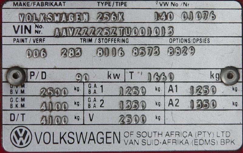
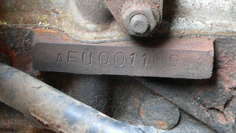
90kW 2.3i "AFU" engine
AAY - 2.5i - 100kW
ADV - 2.6i - 100kW @ 5200rpm
AFU - 2.3i - 90kW
http://www.brick-yard.co.uk/forum/power-figures-on-the-za-engines_topic61580.html
2.3 is 122 bhp (90 Kw) & 185Nm 2.5 & 2.6 are the same at 136 bhp (100 Kw) & 200 Nm The 2.6's get max torque at 3000 rpm & the 2.5's are at 3500 rpm.
http://www.syncrosa.co.za/forum/showthread.php?tid=1514, The 2.6 has a stroke of 95.5 and bore of 82.5, which gives 2 553cc. Compression ratio is 10:1.
The 2.3 and 2.6 use the same block, stroke is 92.7? for the 2.3 and 95.5 for the 2.6.
According to Audizine the 5 cylinder engines weigh about 185 kg.
https://volkswagen.7zap.com/en/za/typ+2/t2/2003-275/1/.
These vehicles were fitted with either a 4-speed or a 5-speed gearbox. The top gear (4th or 5th) ratios are the same (0.85) and the differentials are the same too -- so the five speed box won't make you go any faster. The first gear on the 5 speed box is a bit more powerful, and of course you get more options (I find that 3rd is sometimes too strong up a hill while 4th is not strong enough, with the 4-speed box).
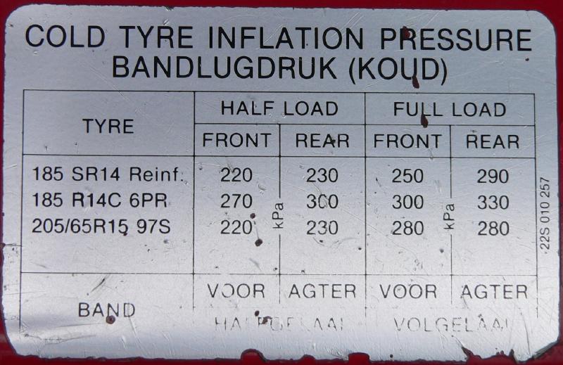
Our Kombi came with 185R14C tyres (80 profile) but we're now running 195R14Cs.
| Size | Diameter | Circumference | Revolutions |
|---|---|---|---|
| 185R14C | 652 | 2047 | 489/km |
| 205/65R15 | 648 | 2035 | 491/km |
| 195R14C | 668 | 2098 | 477/km |
| Engine | 4.5 litres 20W50 |
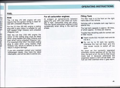
| Fuel tank | 85 litres |
| Cooling system | 17.5 litres, 20% G12 coolant |
| Gearbox | 3 litres |
The sump plug takes a 14 mm copper washer.
Standard battery is a 647 but these days they recommend a 651C. More capacity at about the same cost.
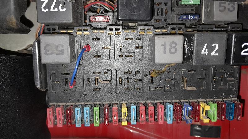
From Microbus Wiring 5.pdf
|
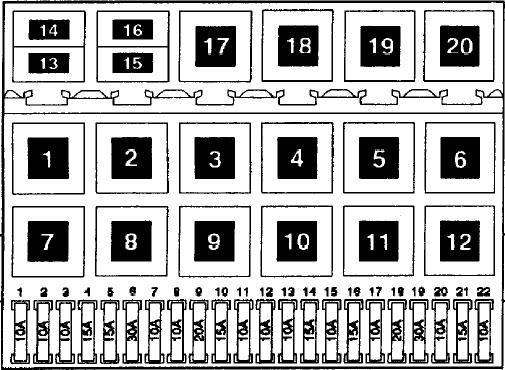
Relays

 1 - Main Relay (53)
 2 - Rear Wash / Wipe (not fitted)
 3 - Not used
 4 - X-relief relay* (18)
 5 - Coolant shortage / temperature switch unit (42)
 6 - Hazard light relay (21)

 7 - Radiator fan 1st stage (53)
 8 - Intermittent wash / wipe (19)
     (not fitted - bar between pins 4 and 5)
 9 - Not used
10 - Not used
11 - Single tone horn relay (53)
     (not fitted - bar between pins 2 and 4)
12 - Not used

13 - Thermo-fuse, 20A, central locking (not fitted)
14 - Fuse, 20A, main beam headlights
15 - Fuse, 10A, instrument lights
16 - Fuse, 30A, radiator fan

17 - Fuel pump relay (53)
18 - Main beam headlight (53)
20 - Fuel gauge damper module
* The X-relief relay cuts all non-essential circuits while the engine is cranking.
|
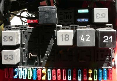 (Not all the original fuses, doesn't quite match the paperwork) |
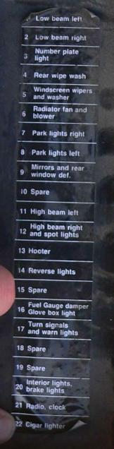
The fuse cover sticker is... not quite right. It doesn't mention the fuses for the fuel injection system.
|
|
I had problems with the battery running flat. Turned out to be the aftermarket radio / PA system my father had installed. But for the record.
| Motronic control unit | 600uA |
| LCD Clock | 2.4 mA |
| Immobiliser | 4.2mA / ~7mA when LED flashes |
It's best to get all the basics right. Your bus most likely had a Dreaded Previous Owner, which means a lot of things could be different from what one might expect. The timing belt might even be off by a tooth or two, I've been told.
1. Distributor. Trace the #1 plug wire to the distributor cap, it should be towards the back (you're standing at the back. This is a VW. Front is front) of the distributor and slightly down from centre. But remember the DPO, the distributor could be fitted any way around.
2. Timing marks. There's a line on the back of the camshaft pulley that aligns with the top of the block for TDC. Pull the #1 plug, get a sosatie stick or something, and position the piston at the top of its stroke with the rotor pointing roughly at where #1 cylinder is on the distributor cap. You should be able to see the little line on the back of the camshaft pulley (where the back of the pulley is towards the front of the vehicle). If the line's not matching piston #1's TDC, your timing belt might be on wrong.
Now check whether you can see the TDC timing mark on the crankshaft pulley. Look through the hole behind the number plate. You will most likely need to clean things up a bit, use tip-ex or something to highlight the mark. They say that the pulley has a rubber bushing and that the whole thing can slip so that your TDC mark is no longer at TDC, in which case you would need to make your own marks, or fix the pulley.
With a 135mm pulley diameter, six degrees BTDC is 7mm on the circumference, so make a second mark 7mm to the right of TDC. I have one of those timing lights where I can set the advance on the light but I don't trust the damn thing.
To set the timing, you need to bridge pins 2 and 4 on the Diagnostic Plug. Rev to 2000 rpm and set the timing to 6 degrees BTDC. Microbus Timing.pdf, extract from Owner's Manual, http://vwclub.co.za/forum/viewtopic.php?t=46087.
Goldwagen will sell you a brand new distributor. "WAG Original Spare Parts" nogal. Their part number is A4671. Cost R635 in May 2017.
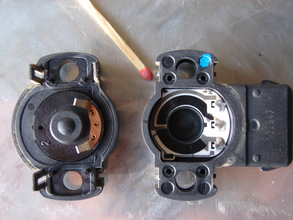
This thing won't work. Can't work, as a matter of fact. Here's why and how to fix it.
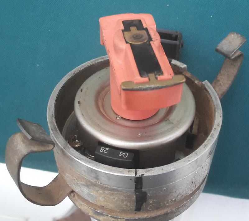
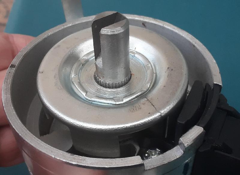
This is the original VW distributor (0 237 522 015, 034 905 205h). They were nice and put a mark where cylinder #1 is (this lines up with the distributor cap).
Note the Hall Effect Sensor and the interruptor plate. Note the #1 mark. Note the position of the rotor. The distributor turns clockwise, and as the interruptor plate enters the Hall Effect Sensor the coil fires and HT goes via the center pin on the distributor cap via the rotor to cylinder 1.
All fair and well.
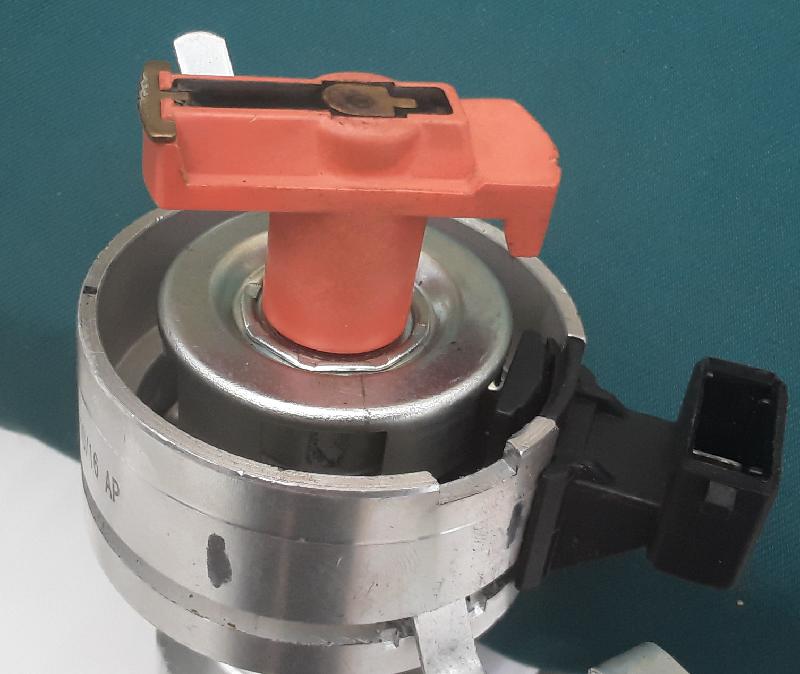
Here's the WAG replacement. They moved the Hall Effect Sensor to the other side, to save some money. It's actually a good idea, the original placement of the Hall Effect Sensor dates from when distributors had a mechanical advance.
Unfortunately they didn't change the position of the slots in the interruptor plate. It's kind of tricky to see on the photograph, but you can check it out on the real thing (because maybe by the time you buy one they've fixed it). You need to mark cylinder #1 yourself, fit the cap and trace a line down from the tower, mark the body with a koki, turn the rotor and look at the interruptor plate. In my photograph you will see that the slot (OK, it would have been better if I'd put the rotor on, but you can trust me on this) is just starting to point at #1, while the interruptor place is fully inside the Hall Effect Sensor.
I thought maybe their Hall Effect Sensor inverts the signal, but I checked, it doesn't.
It is possible to drive out the pin at the bottom, remove the distributor shaft, use a hydraulic press to press the interruptor plate off the shaft, turn the plate 36 degrees or so (mark 1 eyeball required) and put the whole thing back together again. And it works.
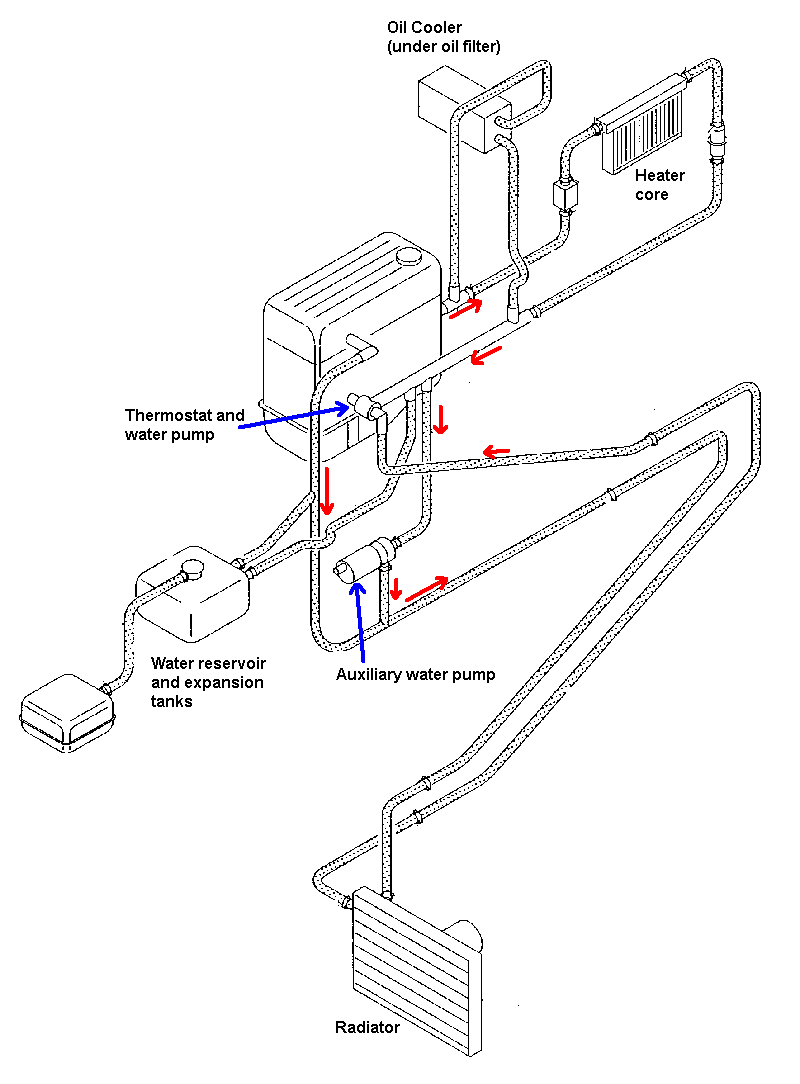
Coolant flow when the thermostat is open. With the thermostat closed there will still be circulation through the heater core and oil cooler but not through the radiator.
The picture below is from https://www.vwclub.co.za/forum/viewtopic.php?t=71913. Note that the flow direction is in fact the opposite from that shown here.
See also https://volkswagen.7zap.com/en/za/transporter/tr/1999-230/1/121-121060/.
F18: 95C and 105C switches, located on the radiator, turns on the radiator fan.
     251 959 481x, where x is A to (at least) K, and as far as I can determine
     indicates the switching temperature. I have not found the suffix for the
     95C and 105C switch points.
F95: 104C switch and (unused) temperature sender, located on the spigot on the top
     right-hand side of the engine. The switch turns on the auxiliary water pump.
     701 919 369B or C (I think).
G27: Dual temperature sender, to ECU and temperature gauge, also located on the spigot.
     357 919 501A (I think), 4 pin, yellow.
My temperature gauge red LED wasn't working. While fixing it I took some notes.
The first function of the blinky light is to draw your attention to a pegged needle. The gauge contains a bi-metal strip with a resistive element coiled around it, as it heats up the bi-metal strip bends and the needle moves. The one side of the heating element goes to the regulated 10V, the other side to the temperature sender unit which is just a variable resistance -- 100 ohm for cold to normal, 33 ohms for kind of hot (approximately).
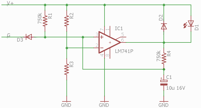
R2 and R3 are 2% precision resistors, I'm not sure I read their values right -- I think 10 720 and 11 520 ohm for 4.8V? Anyhow, they form a resistive divider which puts a reference voltage on the opamp negative input. The positive input goes to the gauge input via the diode, and then there's also the RC circuit to consider.
On startup, the capacitor is discharged so the positive input is at 0, which is lower than the negative input, so the opamp output will be low, turning the LED on (it's a self-blinking LED, there's a little blinker IC inside the LED package). The capacitor now charges up to half of the supply voltage (because of the two 750k resistors) and that's higher than the reference voltage, turning the LED off. With the LED off (and in isolation, i.e. nothing connected to the G terminal) the voltage on the capacitor will now rise to the supply voltage, but of course because of the temperature sender, in practice this will be whatever the gauge / sender combination is doing plus 0.6V for the diode drop.
If the coolant gets hot, the diode will pull the positive input down and the LED will start flashing.
I don't think D2 is really needed. Unlike a relay, the LED won't have an inductive kick. Maybe the idea is to discharge C1 through R4 when the ignition is turned off, but this would still happen through R1 so that doesn't seem likely. Maybe it just seemed like a good idea at the time.
Then comes the more clever bit. Assuming that this gauge is already fitted to your line of vehicles. And let's say you also want the LED to blink when the coolant runs low.
The first solution was for the low coolant sensor to just pull the gauge line low. This pegs the temperature meter and blinks the LED. But it also scares people into thinking their engine overheated when it didn't. So the engineers got clever with the Coolant Level Warning Lamp Control Module. When it senses that the coolant is low, it puts a short pulse (5ms three times a second, give or take) on the analogue gauge line. This is too short to affect the heating of the bi-metallic strip by much, so the needle stays pretty much in the same place. But it's enough to discharge C1 via D3 and... blinky light.
Sensor check
Turn on the ignition. The red LED on the temperature gauge should blink about a dozen times, then turn off. If it doesn't blink, it's broken, fix it.
Now, unplug the water level sender on top of the expansion tank on the right-hand side of the engine bay. Around twenty seconds later, the LED on the temperature gauge should start blinking again. If it doesn't, your #42 Coolant Level Warning Lamp Control Module is broken. The 42 is a latching system, so after plugging the sender back in you will need to turn the ignition off and then on again to stop the LED blinking.
I believe that the engineers over at VW had a reason for everything they bolted to the engine. It cost them money, which could have been profit had that part not been essential. Only hacks remove parts and call ita feature. Of course, our kombi had had a hack-mechanic in its past, who removed not only the pump but also the relay that drives it.
When the engine is hot and you turn it off, the water in the head can start boiling because of the latent heat in the engine, This is not good for the system as a whole, and apparently caused head failures before they added this pump, which circulates water for a while after you shut the engine off.
I bought a new pump and installed it. I also reverse engineered the relay that drives it (J151, controlled by temperature switch F95).
As far as I know the correct part number for this pump is 034 965 561C. It's similar to 251 965 561B (Bosch Auxiliary Water Pump for Volkswagen VR6 Motors found in the Volkswagen Corrado, Passat, Jetta, Golf / GTI, and Eurovan) and 078 965 561 (Golf IV 1.8T and Audi 2.7T). 1K0 965 561J (Auxiliary Water Pump for Tiguan Passat Jetta Golf CC GIt Audi A3 TT Q3) might also work. After all, it's only a pump.
I then found more signs of a hack-mechanic. On the cylinder head water flange there are two temperature sensors. The top one is 357 919 501A, 4 pin, yellow, dual temperature gauge sender, G27 on the wiring diagram. The one side goes to the ECU and the other side to the temperature gauge on the dashboard. The bottom one (F95) in my case was 357 919 501 -- the exact same thing. This is not right. It should be a combined temperature gauge sender (which is not connected to anything) and thermal switch (which comes on at 105 degrees C and is connected to the relay J151).
Some searching (Hella Technical Information) lead me to suspect that the part number for the thermal switch might be 701 919 369B or C. Goldwagen's system crosses this to 357 919 501 i.e. the top sensor, and that's obviously not right. The internet crosses it to a bunch of stuff which I ran past the staff at Goldwagen, finding the Topran 104 109 755 (which is sort of the correct thing but with the wrong pinout -- the thermistor is connected where the switch should be and vice versa) and the Meyle 100 800 9058 (their part number A5366) which has the correct pinout but switches in at 95C instead of 105C. This means the Auxiliary Water Pump will run more often, and I'm cool with that.
(Note: This is for T4 fitted with aircon. Those without aircon use a different two-speed fan motor).
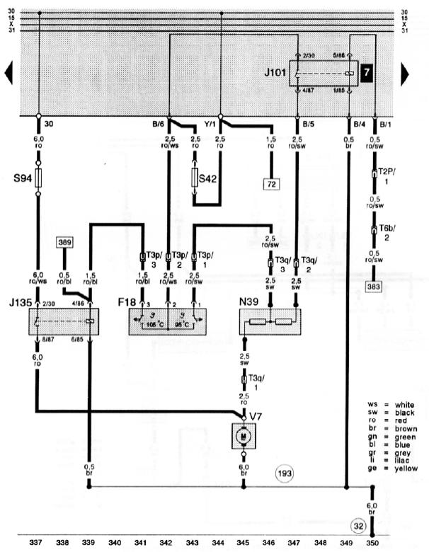
The radiator fan (V7) can run at one of three speeds. Four, if you count "off".
([383] is power when the air conditioner is on. [389] is power when the aircon gas is hot)
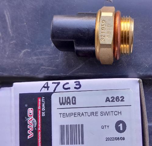
Goldwagen will sell you this replacement switch, which supposedly switches at 85C and 93C. I'm OK with that. Part number stamped on the side is 321 959 481D. Pinout is + 1 2 from the rounded end (with the notch at the bottom).
The resistor that slows the fan down is N39, 251 971 284H. It has two sections, 0.28 Ohm and 0.09 Ohm. It tends to burn out, and it is No Longer Available.
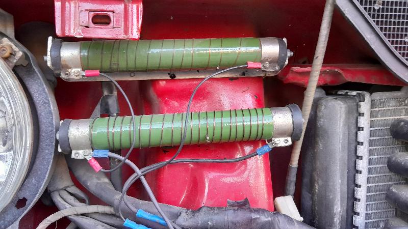
I found some high-wattage resistors, calculated how much of which gauge copper wire I needed, and wound two new resistors. So far, so good.
Some people will try to sell you a resistor which will be 321 905 051, N81 in the wiring diagram. This is a three-section resistor, 0.4 Ohm, 0.85 Ohm and 2 Ohm, and it reduces the speed of the air conditioning ventilation fans. This is not the right part, it might look somewhat similar but it's not interchangeable.
I decided that having the low-speed fan run all the time (and not only when the air-conditioner is on) would be a Good Idea. So.
You can't just jump the 1st stage radiator fan relay (7) directly because it's supplied with "30" power (i.e. always on) and not ignition power. So, remove relay 7 and jumper from relay 2 socket (rear wiper, which I don't have) power "31". Or find ignition power elsewhere if you do have relay 2 fitted.
The thermostat part number is 069 121 113 and opens at 87C. The O ring is 034 121 119, 60mm x 3.5mm.
I also have VW 237 906 311 1 ?
This is a Golf part that's also used in a number of other models, Audi, Seat, etc.
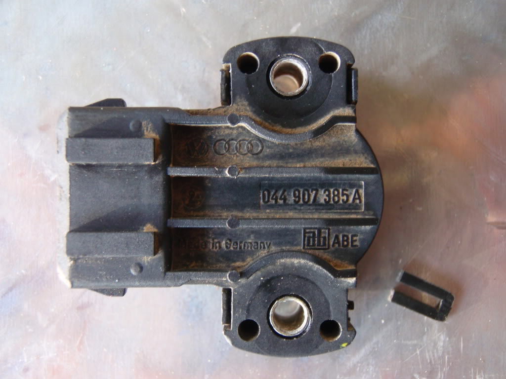
(pics from http://forum.club8090.co.uk/viewtopic.php?f=12&t=83127)
Masterparts equivalent Meat & Doria 83086
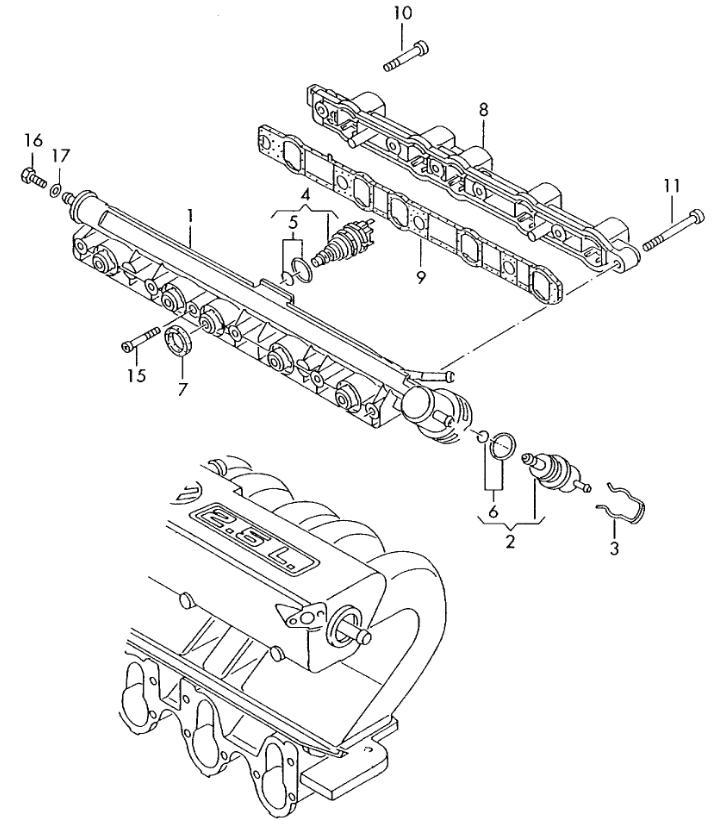 This is actually an assembly with five injectors in parallel.
1   023133322A  Fuel rail                                        1
2   037133035C  Fuel pressure regulator                          1
3   037133047A  Retaining clip                                   1
4   044906031   Injection valve                                  5
5   996133002   Bearing seal                                     1
6   037198031   Gasket set for pressurecontroller                1
7   037133398A  seal ring                                        5
8   22S133313   Fuel line                                        1
9   023971786   Seal                                             1
10  N0147495    Socket head bolt with hexagon socket head M6X40  1
11  N10059801   Socket head bolt with hexagon socket head M6X70  5
15  N0141531    fillister hd. bolt 5X40X25                       1
16  N0102017    Hexagon bolt M4X8                                1
 Nothing from here on down is gospel. I'm also not too sure of anything above...
From http://www.brick-yard.co.uk/forum/wiring-diagrams-or-manuals_topic66993.html
[...]there was an ecu change mid-1997 and again from 1998 onwards, but maybe only remapped for unleaded fuel, judging by the ETKA comments.
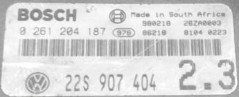
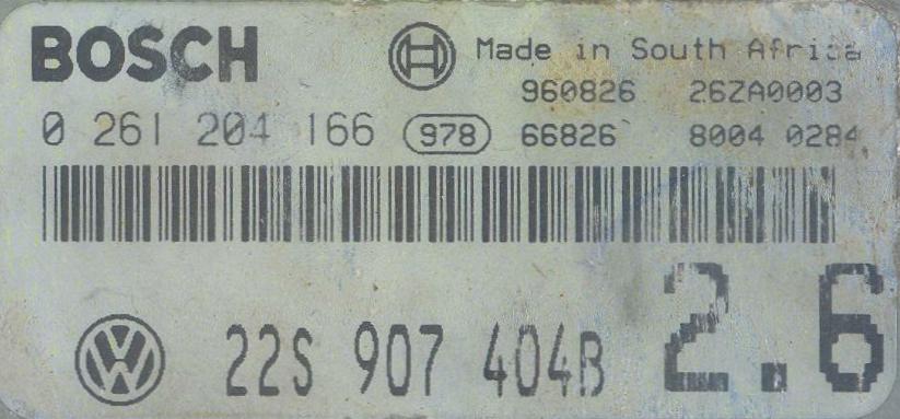
For 2.6:
early version 22S 906 022,
10/95 to 12/97 22S 907 404 B,
1/98 onwards 22S 907 404 D

For 2.3:
22S 907 404 (Volksie only), later suffix A or C, same dates for changeover.
Also, https://volkswagen.7zap.com/en/za/typ+2/t2/2003-275/9/906-906010/
22S 906 022  2.6  to 09/95
22S 907 404B 2.6  10/95 - 12/97
22S 907 404D 2.6  01/98 -

22S 907 404  2.3  Volksiebus 10/95 - 12/97
22S 907 404A 2.3  ?
22S 907 404C 2.3  01/98 -
As I understand it, in 1998 they changed the system to use MPI (individually driven injectors) and this is the "Metal Rail" fuel rail and the -C and -D suffix ECUs. 22S 906 022 and 22S 907 404, -A and -B would be single injector drive "plastic rail" (there are still five injectors). Here's a picture of a late-model engine bay with MPI.
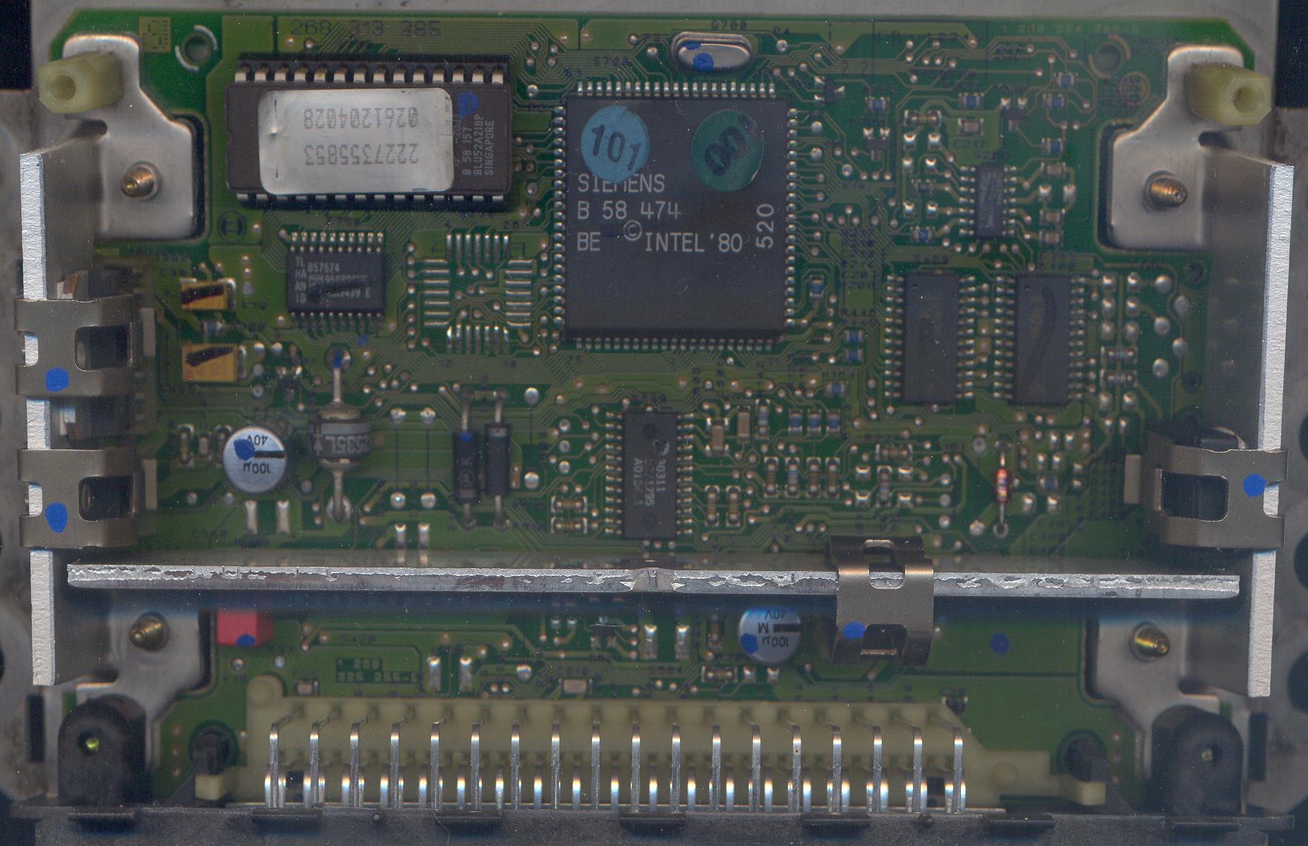
| 22S 907 404A 2.3 | 22S 907 404B 2.6 |
|---|---|
 |
 |
 |
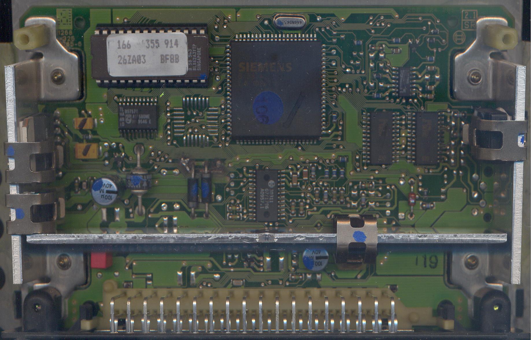 |
| The EPROM is a 27512-equivalent 64k x 8 device. | |
2227355853
0261204028
This EPROM contains the following identifying strings: 0261204028 26ZA0002 22S907404A 0261204027 MAY 1995 0261204028 2227355853 M15 004 |
166   355 914
26ZA03   BF8B
This EPROM contains the following identifying strings: 0261204166 26ZA0003 22S907404B 0261204165 SEP 1995 0261204166 2537355914 M15 004 |
From http://vwclub.co.za/forum/viewtopic.php?t=46087
It is a bosch motronic unit.
It has a singel feul rail that will pulse all at once per fire point [5 cyl]
as per panic.It has a idel steppe motor 1xt.b sensor ,water temp , air temp and manifold sensor.

How to adjust system.
1x adapter cable from vag plug to the 5pin plug in the picture as seen.
To get into the ecu the ign must be switched on
Enter ecu [01] then go adaption [10] enter channel 01
Start bus [make sure battery stong or it will kick you out]
Adjust the value in channel 01 up or doun [up richer lower leaner]
Apparently these ECUs use the KW1281 protocol.
|
|
Back | (This page last modified 2024-12-17) |