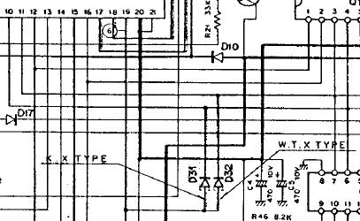
- K : 10 kHz / 5 kHz steps in FM1 / FM2
- X : 25 kHz / 5 kHz steps in FM1 / FM2
- W,T : 25 kHz / 12.5 kHz steps in FM1 / FM2
- K,X : 144.000 MHz to 147.9999 MHz
- W,T : 144.000 MHz to 145.9999 MHz
K   : D31
W,T : D32
X   : both diodes
The TR-9000 is a 2m all-mode transceiver that covers 144 - 148 MHz.
As with most all-mode transceivers, there are basically two transceivers in the box, one for FM and one for SSB/CW. Very little is shared between the two. Also, as with many FM transceivers, there's very little shared between the transmitter and receiver, it's effectively an independent transmitter and and independent receiver in one box. On the SSB side the crystal filter is shared between the transmitter and receiver, that's about it.
Interestingly, the CW mode uses the FM transmitter and the SSB receiver (well, it makes sense, actually. Unmodulated FM is just a carrier).
The low power mode (which mine doesn't have -- it's a W) is also interesting. The output transistor is protected by a monitor circuit that turns down the power if there's a mismatch. Making this monitor more sensitive limits the output power on FM and CW. Of course this doesn't work on SSB, therefore SSB works in high (normal) power only.
Everything is run by a uPD650C microcontroller controlling a PLL, so repeater offsets, scanning and memory channels are easy.
There are at least five different models, being K (USA), T (UK), W (Europe), X (Australia) and G (Japan). Of these, the W and G models are visibly different.
Programmed differences (you can change this by re-wiring the diodes)
K : D31 W,T : D32 X : both diodes |
|
My TR-9000 is fitted with a ZS6MRK tone board at 88.5Hz.
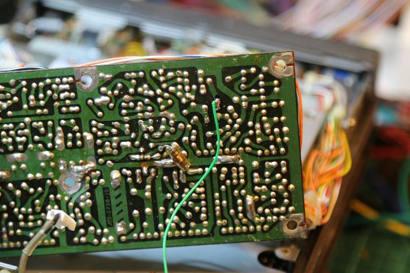
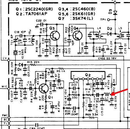
CTCSS signal is injected at the junction of L1 and C16 on the TX unit, just before the modulation pot.
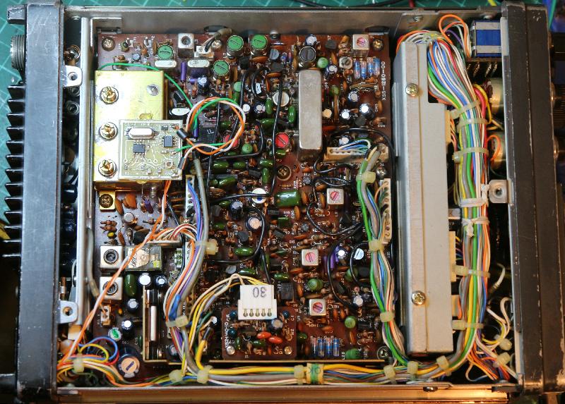
The actual CTCSS unit is fitted on the other side of the radio, close to the speaker.
N9XLC links to the Service Manual on Scribd, but you need to join them to download it. I got mine from Maurice, he's a nice guy and a good person to deal with. The schematics in both the User Manual and the Service Manual are very difficult to read. Fortunately radiomuseum.org has a nice set.
Setting deviation using the Bessel Zero.
The uPD650C is a member of the uCOM43C Series 4-bit microcontrollers, with 2k x 8 ROM, 96 x 4 RAM, and a whole lot of I/O. That's all I have.
|
|
Back | (This page last modified 2020-04-13) |