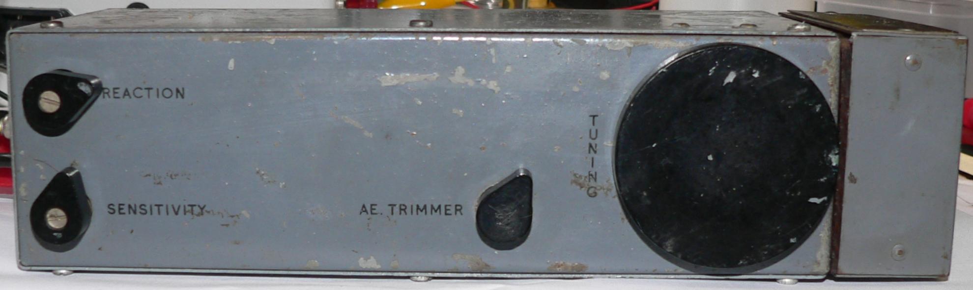
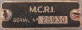
December 2013: Bought this set from the Kalk Bay Trading Post for R 1 150. #25930.
|  |
The "Original Manual" at the Crypto Museum is a combination of the original manual and a four-page supplements created later, when surplus sets were sold to the public. I'd wager that the drawing of the fellow in the trench coat was added at this stage to make the set more appealing -- it's a midget receiver, not a "spy radio".
Not only did Clydesdale Supply Co got some values wrong in their supplement, but the component layout on page 7 lists two C6Bs. This kept me busy (and confused) for a while.
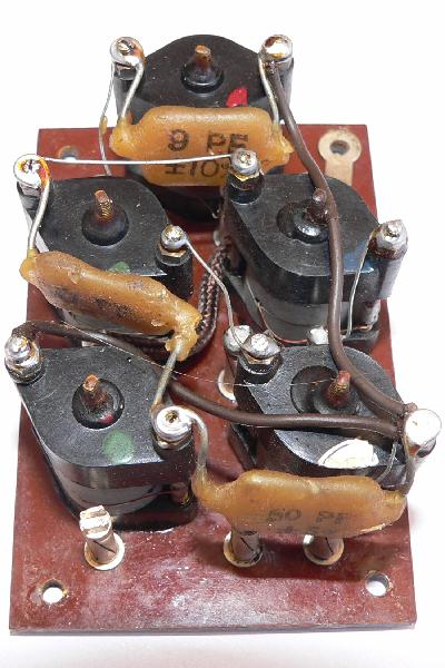
By tracing the
circuitry I found that the one on the right is in fact C6B. The one on the left is connected
to the "black" common rail and to R12A, which makes it C6D. So then, the capacitor labelled
C6D in the component layout is...
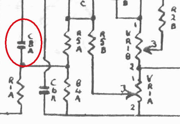
this one. Your guess is as good as mine. Elimination shows that it could be C8B, but the
schematic definitely reads "A". So I concluded that this is in fact C8A, and that there is
a further error, the capacitor labelled C8A on the chassis layout is in fact C8B.
This makes sense because:
The schematic on VK2BV's page has C8A and C8B the way I think they should be, but the area where the coils plug in looks wrong -- like someone started with half a schematic and drew that part in incorrectly.
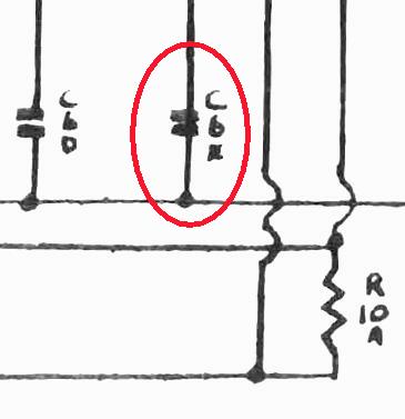
And then there's this. C6E. The component list does not list a C6E. It does however list a C5E which is not on the schematic. So either this is C6E, 0.1uf, and the parts list is incorrect, or this is C5E, 0.05uf, and the schematic is wrong. On the radiomuseum.org schematic (which I can't reproduce here) this capacitor is called C8 and it's 0.05u. C5E it is.
I cut-and-pasted and contrast enhanced and photoshopped the schematic from the manual. It's much more readable now, especially if you print it on A3.
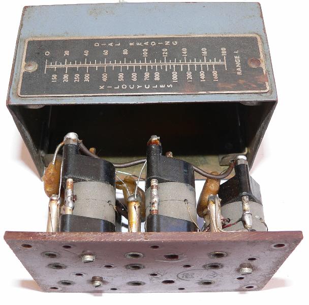
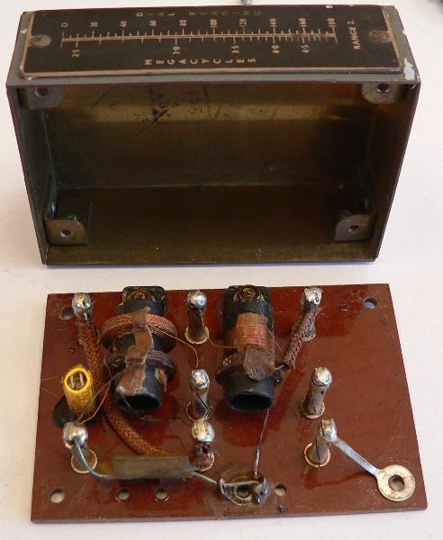
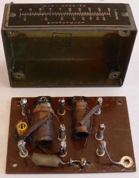
Capacitors often go bad with age. Even Apple Mac computers from 1990-ish have problems, so a set from 1943 will definitely need some work.
The MCR1 uses both mica (doesn't go bad) and paper (does go bad) capacitors. I was worried that I would lose some originality replacing caps, but...
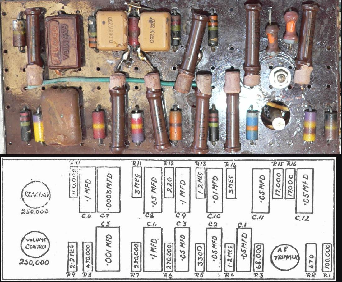
... turns out some butcher's been here before me. The resistors all look original (most with body dot tip marking) but it looks as if most of the capacitors have been replaced. With what appears to be tubular ceramic and poly capacitors (good) with completely the wrong values (bad). C8A is good, C5E and C6A are close, the rest are either five or ten times too small.
| Image refdes | Schematic refdes | Value | Value fitted |
|---|---|---|---|
| C1 | C6D | 0.1u (error on p20) | 10n (0.01u) |
| C2 | C5C | 0.05u | 10n (0.01u) |
| C3 | C5D | 0.05u | 10n (0.01u) |
| C4 | C6C | 0.1u | 10n (0.01u) |
| C5 | C7A | 0.001u | Original |
| C6 | C6B | 0.1u | 10n (0.01u) |
| C7 | C9A | 0.003u | Original (Mica) |
| C8 | C5E | 0.05u | 0.068u |
| C9 | C6A | 0.1u | 0.082u |
| C10 | C8A | 0.01u | 10n (0.01u) |
| C11 | C5B | 0.05u | 10n (0.01u) |
| C12 | C5A | 0.05u | 10n (0.01u) |
The Royal Signals website has some pics of what appears to be an untampered-with MCR1. Serial number is 55792 (as far as I can tell) which explains the more modern resistors.
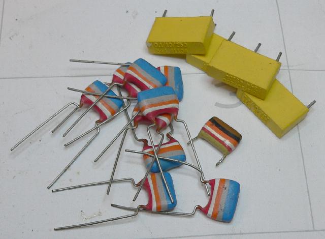
I always admired the Elektor magazine projects from the eighties, they went out of their way to make good-looking assemblies. I'm not going to the same length, but I had these nice colourful poly caps in stock, might as well use them. OK, the value is a bit high, 68nF instead of 50nF, but a bit more capacitance is not a problem in non-critical (bypass) positions. Unfortunately the only 100nF caps I had in stock are boring yellow boxes :-)
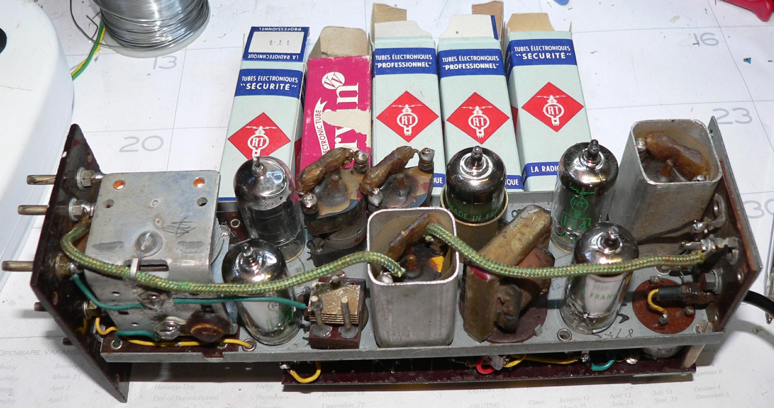
The slaughter continues. Of the five tubes in the set, only one is of the correct type, and its filament is open circuit.
| Should be | Was | |
|---|---|---|
| V1A | 1T4 | Mullard DF96 (pin compatible, higher voltage rating, 25mA heater) |
| V2A | 1R5 | DK92? (hand labelled) (heptode) |
| V1B | 1T4 | Tung-Sol 1T4 (filament open) |
| V1C | 1T4 | 1S5? (hand labelled) |
| V1D | 1T4 | Haltron 3S4 (centre-tapped 2.8V filament) |
The mind boggles.
(In fairness, our DPO also rewired the whole thing to put the filaments in parallel, which means that the 25mA heater and maybe even the 2.8V filament is sort-of-OK, but since the tubes don't use indirectly-heated cathodes, the grid bias depends on the position of the tube in the chain. Which also explains the order that the filaments are connected in -- V1B has the most negative grid bias and V1C has the most).
Datasheers from scottbecker.net, 1T4 and 1R5.
Having found some errors in the manual, I thought I'd list the component values as I think they should be.
The original manual has strange reference designators (refdes). All components of the same value gets the same refdes, with a prefix starting at A. This makes sense, except that one would then expect that two capacitors with the same capacitance but different voltage ratings should have different refdes, and this is not the case with C8A (250V) and C8B (550V).
In any case, rather than add to the confusion by renaming the components (as Clydesdale Supply Co did), I decided to stick to the original refdes.
| Refdes | Clydesdale | Value | Location | Notes |
|---|---|---|---|---|
| C1A | 100p | Between coil plug-in board pin 7 and R1A | ||
| C2A | 50p | Between V1B.2 and V1C.6 | ||
| C2B | 50p | Between coil plug-in board and V1A, next to tuning knob | ||
| C2C | 50p | On IFT L1A | ||
| C2D | 50p | On IFT L1B | ||
| C2E | 50p | On coil plug-in board | ||
| C3A | 300p | On aerial coil L21A terminals | ||
| C4A | Fixed cap, not trimmer as manual indicates | On L2A terminals | ||
| C5A | C12 | 0.05u | Circuit board | |
| C5B | C11 | 0.05u | Circuit board | |
| C5C | C2 | 0.05u | Circuit board | |
| C5D | C3 | 0.05u | Circuit board | |
| C5E | C8 | 0.05u | Circuit board | |
| C6A | C9 | 0.1u | Circuit board | |
| C6B | C6 | 0.1u | Circuit board | |
| C6C | C4 | 0.1u | Circuit board | |
| C6D | C1 | 0.1u | Circuit board | 0.01u on Clydesdale layout (Supplement page 4) |
| C7A | C5 | 0.001u | Circuit board | |
| C8A | C10 | 0.01u | Circuit board | |
| C8B | 0.01u | Between standoff near V1B/V1C/V1D and chassis | Error: on page 7 this cap labelled "C8A" | |
| C9A | C7 | 0.003u | Circuit board | 0.0003u on Clydesdale layout (Supplement page 4) |
| C10A | 0.005u | Output transformer terminals | ||
| R1A | 470k | On terminals next to tuning knob | ||
| R1B | R8 | 470k | Circuit board | |
| VR1A | none | 250k | Circuit board | |
| VR1B | none | 250k | Circuit board | |
| R2A | R1 | 100k | Circuit board | |
| R2B | R10 | 100k | Circuit board | |
| R3A | R16 | 18k | Circuit board | 17k on Clydesdale layout (Supplement page 4) |
| R3B | R15 | 18k | Circuit board | 17k on Clydesdale layout (Supplement page 4) |
| R4A | R14 | 3.3M | Circuit board | 3M on Clydesdale layout (Supplement page 4) |
| R4B | R11 | 3.3M | Circuit board | 3M on Clydesdale layout (Supplement page 4) |
| R5A | R13 | 1.2M | Circuit board | |
| R5B | R4 | 1.2M | Circuit board | |
| R6A | R7 | 220k | Circuit board | |
| R7A | R9 | 2.2M | Circuit board | |
| R8A | R6 | 270k | Circuit board | |
| R9A | R2 | 470 | Circuit board | |
| R10A | R5 | 330 | Circuit board | 3300 on Clydesdale layout (Supplement page 4) |
| R11A | R12 | 220 | Circuit board | |
| R12A | R3 | 68k | Circuit board |
I measured all the resistors while I had the whole thing apart, quite a few of them had drifted up in value.
| Refdes | Should be | Measures | Error | Parallel fix | Use | New value | Error |
|---|---|---|---|---|---|---|---|
| R1A | 470k | 540k | 15% | ||||
| R1B | 470k | 508k | 8% | ||||
| R2A | 100k | 124k | 24% | 516 667 | 470k | 98.1k | -2% |
| R2B | 100k | 125k | 25% | 500 000 | 470k | 98.7k | -1% |
| R3A | 18k | 20k | 11% | ||||
| R3B | 18k | 33k | 83% | 39 600 | 39k | 17.9k | -1% |
| R4A | 3.3M | 3.4M | 3% | ||||
| R4B | 3.3M | 3.66M | 11% | ||||
| R5A | 1.2M | 1.48M | 23% | 6 342 857 | 5.6M | 1.17M | -2% |
| R5B | 1.2M | 1.27M | 6% | ||||
| R6A | 220k | 209k | -5% | ||||
| R7A | 2.2M | 2.91M | 32% | 9 016 901 | 10M | 2.25M | 2% |
| R8A | 270k | 262k | -3% | ||||
| R9A | 470 | 456 | -3% | ||||
| R10A | 330 | 315 | -5% | ||||
| R11A | 220 | 245 | 11% | ||||
| R12A | 68k | 76k | 12% |
I like the look of the body dot tip resistors, so I elected to keep them and add a resistor in parallel under the circuit board to tame the drift in the cases where the error was more than 20%. Yes, they'll probably continue drifting. I don't plan on using the set much.
I made a list of all the connections (nets) to help me rewire this thing correctly.

New capacitors (I kept one of the tubular capacitors, C7A, that was the only replacement cap with the correct value. I did measure it to make sure though).
New tubes from eBay, and we're ready to go.
The battery is a dual HT/LT unit with 90V HT and 7.5V LT, using a Type E connector but with different pinouts.
This doesn't match any table I've been able to find. See for example the Battery Equivalent Chart at UK Vintage Radio or the Thompson-Brown Family's information. Only one 90V + 7 1/2V with an eight pin socket, that's not it.
The DZ Birger site has a replica battery, "Battery, Dry HT./LT. 90v/7 1/2V Type No. E.R.W. 1520".
Dimensions are 2 3/8" X 7 1/2" X 2 7/8".
Here are two threads on UK Vintage Radio on building replacement battery packs. And here are some clear instructions and pictures from Radiomuseum.
Or you can make a mains adapter, which is what I did. I only needed to buy two 220uF 63V capacitors, everything else came from the junkbox. The two 470uF capacitors don't need to be 63V, they only have about 20V over them so 35V is fine. I also had a 100u 100V capacitor so I didn't need the trick with the two capacitors and equalizing resistors.
On the filament side I used 1k + 100R variable for R6, this gives about 6.9 to 7.5V and I set it to 7.2 with no load, it drops to about 7.1 with the filaments connected.
|
|
Back | (This page last modified 2014-10-30) |