Historical Info -- my way of life changed so I no longer drive a Land-Rover :-(
|
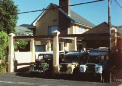
Groenie, Spikkels, White LR
|
I don't drive a Land-Rover because it's a 4x4.
I drive a Land-Rover because it's a way of life.
Driving a Land-Rover is fun. Don't believe
me, read
this posting
from the Land Rover Owner Mailing List. (This should
also give you an idea of my definition of 'fun' :-)
|
Main --
Spikkels --
Tech --
Trips --
Tips --
Recipes
Tips, tricks, and general stuff that might be useful to you
Scope
I know a bit about Series I, II, IIA and III Land-Rovers.
Anything newer than that is not retro enough :-)
The info here is based on the Land-Rovers I
own / have owned / drive on a daily base. Which are: a 1955 Series I,
a 1959 Series II, a 1963 Series IIA Forward Control, and a 1965-ish Series IIA.
Mechanically, the SII is much the same as the SI that preceded
it. The body changed, to the shape that most people are familiar
with. But the SII axles and gearbox are Series I components. The
SII came with a 2 1/4 engine that is almost but not quite the
same as the 2 1/4 everyone is familiar with. When the SIIA got the
2 1/4 diesel engine, the 2 1/4 petrol engine was upgraded to the
same size main bearings as the diesel. Which makes the standard
2 1/4 petrol engine nice and strong. But of course it also made
an orphan of the SII 2 1/4, which was only available in 1959 and
1960. The bearings for this engine is difficult if not impossible
to find.
The SIIA got the upgraded gearbox, with the thicker layshaft. And
the front axle changed, the steering arms are attached to the bottom
of the casings (non-pendant, they call it).
Somewhere close to the end of SIIA production, the wheel nuts changed
to UNF (from BSF). SIII wheel nuts are UNF. And the SIII got a new
gearbox, with syncro on all four gears. Also, the hydraulic clutch
and release bearing mechanism on the SIII is different, I don't know
why they changed it.
Conversions
1 HP = 0.746 kW    1 kW = 1.341 HP
1 lb.ft = 1.35 Nm  1 Nm = 0.741 lb.ft

1 gallon (British) = 1.2 gallon (US) = 4.54 l
1 Bar = 100 kPa = 15 psi, give-or-take.
December 2003
Series LR bellhousings
If you phone Gilo Engineering (In South Africa, YMMV) and ask for an
adaptor plate, they'll ask "4 cylinder or 6 cylinder?".
The Series One, Two and Three bellhousing have 12 holes, spaced at
give-or-take 30 degrees
(it may, of course, be exactly 30 degrees, this is not important).
For the 4 cylinder 2 1/4 engine, there's a stud at 12 o'clock.
For the 6 cylinder 2.6 engine, the studs are moved give-or-take
15 degrees, so there is no stud / hole at 12 o'clock.
The Series I 4 cylinder (2 litre) engine has the same configuration
as the 6 cylinder, it's the same design (semi-side valve, beautiful
engine, but I digress).
Dual Battery setup
There are many schemes for charging two batteries from one alternator.
I use a manual one, a relay powered from the switch on the SII dashboard,
which I turn on to charge the fridge battery. Similar to Johann Hugo's
schematic which you will find under "Homemade Equipment" on
www.overland.co.za (direct
link here).
But then the idea hit me. I'm carrying a spare alternator in any case,
ever since I lost an alternator in Zambia. Why not mount said alternator
on the engine permanently and use that to charge the fridge battery? Less strain
on the primary alternator, complete isolation without voltage drops,
and I will need some simple bridging box to fix things if one of the
alternators pops. This will of course fall back to the scheme I'm using
at the moment.
I'll probably implement this in the Forward Control.
Rim Offset
SAE specifies that a positive rim offset narrows the track.
Yes, this is strange. There's a whole writeup archived
on the
DeTomaso list.
Anyway, inset is positive offset, outset is negative offset, and the center
line is half of the rim width. Which is measured between the rim flanges, on
the tire (in) side.
This table comes from the LRO mailing list. I've changed the table headings
to be in line with what I've said above.
| |
Rim Width |
Distance from
outboard bead to
mounting face |
Distance from
inboard bead to
mounting face |
Offset from
centre line
(inwards)
|
|---|
| SWB |
5" |
0.75" |
4.25" |
1.75" |
| LWB early |
5.5" |
0.75" |
4.75" |
2" |
| LWB late |
5.5" |
1.25" |
4.25" |
1.5" |
| LWB split |
5.5" |
1.375" |
4.125" |
1.375" |
| FC early (SIIA) |
6.5" |
2.75" |
3.75" |
0.5" |
| FC late (SIIB) |
6.5" |
3.25" |
3.25" |
0" |
On the other tentacle, my SII & IIA parts catalogue (605957) gives
|
Part #
|
Use
|
Description
|
|
231601
|
88, Except NADA
|
Road wheel, well base rim type
|
|
526753
|
88, NADA
|
Road wheel, 6L x 15"
|
|
272309
|
109, offset from rim centre line 1 13/16" (1.8125")
|
Road wheel, well base rim type, 5.5" x 16"
|
|
568966
|
109, offset from rim centre line 1 5/16" (1.3125")
|
Road wheel, well base rim type, 5.5" x 16"
|
|
217267
|
Optional on 88 models
|
Road wheel, detachable rim type
|
|
526753
|
Optional
|
Road wheel for sand tyre
|
January 2004
Setting your timing, and notes on centrifugal and vacuum advance
Distributors wear, just like any other moving part of your engine.
If you're checking the timing with your timing light, and the little
mark is not dead steady at idle, you probably have a worn dizzy.
Take off the distributor cap and rotor and give the shaft a wiggle.
Does it move side-to-side? New bushings required. Up-and-down motion
is bad too -- the driving gear wants to climb out and that
causes a wandering timing (exception is when the driving gear is retained
by some other means, and the distributor slots into that. Or when the
distributor is driven from the camshaft. But in general, any movement is
bad.)
Remove the points carrier plate. What's the pivots for the weights
look like? Probably needs to be replaced.
With the engine running and the vacuum pipe plugged at the
carburettor, slowly increase the revs while watching the timing
mark. It should advance slowly, and return to the original setting
when you drop the revs to idle. It should also advance by the
same amount every time you do this. If not, your weights are sticking.
If you're near Cape Town, take the dizzy to Gary (082 962 5677) in
Capri Village (Near Fish Hoek). He does a great reconditioning job.
OK, now to actually set the timing. The manual will tell you to
line up some mark with some pointer. Sure, when the engine was new,
those marks were accurate. But maybe the pointer is bent. Or you
have a different pulley with the mark in a different place (case
in point, VW 1700 has different timing marks for carburettor and
fuel injection models). And, if you changed the cam, the optimum
timing point probably changed too.
So, hook up a vacuum gauge. No, not to the vacuum advance line,
that's ported vacuum and not what you want. Use the line
going to the brake booster. You should have a vacuum gauge on
the dashboard anyway :-)
Fiddle with the timing to maximize the vacuum reading. That's
where the engine wants to run. I generally retard the timing
to drop the vacuum a bit (5 - 10 kPa) but maybe I'm overly
cautious...
Your mechanical advance should add about 25 degrees total, which
should be "all in" by 2000 to
3000 rpm. But again, ask the engine. With the vacuum advance still
disconnected, find a hill, floor the throttle, try to make the
engine ping. If you can, you have too much advance. Either
retard the dizzy (easy, but not optimal) or change the mechanical
advance (stronger springs, this becomes a bit esoteric.)
Your vacuum advance should add about 20 degrees (because they
tell me that a total advance of 55 degrees is good, but more
isn't). You need a vacuum pump to test this. And test drive to
ensure you're not adding too much advance. But with the stock
dizzy and a mostly stock engine, you don't need to stress
about this bit.
Just make sure you don't set the timing on the bleeding edge on
a cold day, 'cause it's going to ping madly when it gets hot. Or
when the fuel quality drops, out in the bush.
More about vacuum gauge readings & interpretations
here.
Last note: If you break it, I don't want to know about it, and you
get to keep all the pieces :-)
January 2004
Ramblings on Power and Torque
Engines are rated in terms of power (in kW) and torque (in Nm).
Torque measures the (twisting) force applied to something, be it
a wheel or a bolt. It's defined in terms of a lever arm, if you
apply a force of 1 Newton to a 1 metre long pipe clamped in a
vice, you are applying one Nm to the vice.
Important point: You can apply a lot of torque without doing any
work (lean back on your chair. That's it, torque on the chair,
no work being done... :-)
Seriously, if you're undoing a bolt. You apply increasing torque
until the bolt "breaks" loose. The torque you applied up to the
point where the bolt loosened did not do any work.
Power is the rate of doing work. Running up a flight of
stairs takes more power than walking up.
When it comes to engines, power and torque are related by the
following formula :
| | Torque x RPM |
| Power = |
|
| |
9549 |
Where power is in kW, torque is in Nm, and the 9549 is the result
of using those units (for HP and ft.lb it's 5252).
Of course, we all want to increase the power and torque of our
engines :-) A longer stroke gives more torque, but a long stroke
engine is a low-revving engine (there's a limit on how fast the
piston can move in the bore. And a long stroke means that it
takes longer from the one end of the stroke to the other. Which
is half a revolution). Long stroke engines are also less efficient
(as far as I know, relatively "square" engines
"square" : bore = stroke) are the most efficient).
Of course, to increase the power, you can also rev the engine higher.
Which is what Formula One racers do. Higher revs = more wear = engine
rebuild after each race.
As Robert Heinlein said,
TANSTAAFL.
Alternators
Bosch Voltage Regulator
Just for fun, I reverse engineered the voltage regulator off a
Bosch Alternator from a VW Golf. See my
reverse engineering
page for details.
Bosch codes
A typical Bosch alternator has a description code like
N1 > 14V 40/110A.
N1  : Size (G, K, N, T, size increases alphabetically)
>   : Alternator rotates clockwise
14V : Standard (they make 28V alternators too
40 : Output current at 1800 rpm (alternator RPM, not engine RPM)
110 : Output current at 6000 rpm.
Studs
Before installing a stud, countersink / bevel the edge of the stud holes to a depth of
about 1mm. This acts as a stress relief at the surface of the casting and prevents the
metal around the hole from being raised.
Essential for aliminium, still a good idea for steel or cast iron.
And the loctite won't work if the holes are oily or dirty -- I use carb cleaner
to clean the holes and the studs before assembly.
Brakes
Q : Dear Dr R. Lover, the brakes on my Series II pull to the left
sharply. It's at its worst first thing in the morning, and it seems to
get better after a bit of a drive. But the next morning it's back,
just as bad as before. I've managed to lock the left front wheel up
solidly, which scares the shit out of me and everyone else on the
road. Please help!
A : You have brake fluid on the shoes! Just a drop or two from
a leaky brake cylinder is all that is needed.
Put the front axle on stands, and pull the drums, shoes and cylinders.
Haul the whole mess off to CBS, get them to re-line the shoes, skim the
drums if required, and stainless steel sleeve the cylinders. Get new
rubbers from them. Reassembly is the reverse. Have Fun!
(signed) Dr. Rand Lover.
High Ratio Transfer Box conversion
This conversion works, as far as I can figure it out, because
of a number of coincidences.
The first important thing is that early (Series I) transfer
cases have a small shaft (28mm dia) carrying the intermediate gear.
Later transfer cases have a large shaft (41mm dia).
The second important thing is that suffix "B" boxes have a 2.89
ratio low range, while suffix "C" boxes have a 2.35 ratio.
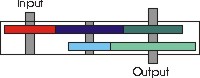
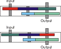
The first coincidence comes in when you realise that you can
swap the input (27 teeth) and
output (31 teeth) gears around
(same tooth pitch) if you move the intermediate gear to the right.
The second and most amazing coincidence is that the low-range
output gear required to make this work is the gear from the
suffix "C" box (36 teeth instead of 39).
Another maybe-coincidence is that, while the high range changes
from 1.148 (31/27) to 0.871 (27/31), the low range changes from
2.347 ((44*36)/(27*25)) to 2.323 ((44*36)/(31*22)) (assuming
you started with a "C" box) -- in other
words high changes but low doesn't.
Of course the insides of the input and output gears are not the same.
The input
gear rides on splines, so you need a spare input gear that is
machined off and inserted into the output gear to become the
new input gear. The output gear is drilled out to fit around
the output shaft.
Number of teeth on gears
Suffix B
Suffix C
Clear as mud? Lemme know if you don't understand. Also let me
know if I figured this out incorrectly (I haven't done this,
understand?)
2005-12-20 : The topic came up on the LRO list again,
read all about it. But note,
there's at least one typo in this email!
Links
