From the advert:
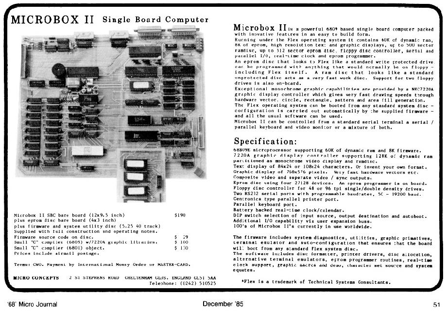
Microbox II is a powerful 6809 based single board computer packed
with inovative features in an easy to build form.
Running under the Flex operating system it contains 60K of dynamic ram,
8K of eprom, high resolution text and graphic displays, up to 500 sector
ramdisc, up to 512 sector eprom disc, floppy drive controller, serial and
parallel I/O, real-time clock and eprom programmer.
An eprom disc that looks to Flex like a standard write protected drive
can be programmed with anything that would normally be on floppy -
including Flex itself. A ram disc that looks like a standard
unprotected disc acts as a very fast work disc. Support for two floppy
drives is also on-board.
Exceptional monochrome graphic capabilities are provided by a NEC7220A
graphic display controller which gives very fast drawing speeds through
hardware vector, circle, rectangle, pattern and area fill generation.
The Flex operating system can be booted from any standard system disc -
configuration is carried out automatically by the supplied firmware -
and all the usual software can be used.
Microbox II can be controlled from a standard serial terminal a serial /
parallel keyboard and video monitor or a mixture of both.

Specification:

68B09E microprocessor supporting 60K of dynamic ram and 8K firmware.
7220A graphic display controller supporting 128K of dynamic ram
partitioned as monochrome video display and ramdisc.
Text display of 84x24 or 108x24 characters. Or invent your own format.
Graphic display of 768x576 pixels. Very fast hardware vectors etc.
Composite video and seperate video / sync outputs.
Eprom disc using four 27128 devices. An eprom programmer is on board.
Floppy disc controller for 48 or 96 tpi single/double density drives.
Two RS232 serial ports with programmable baudrates, 50 - 19200 baud.
Centronics type parallel printer port.
Parallel keyboard port.
Battery backed real-time clock/calendar.
DIP switch selection of input source, output destination and autoboot.
Additional I/O capability via user expansion buss.
100's of Microbox II's currently in use worldwide.

The firmware includes system diagnostics, utilities, graphic primatives,
terminal emulation and auto-configuration that ensures that the board
will boot from any standard Flex system disc.
The software includes disc formatter, printer drivers, disc allocation,
alternative terminal emulators, eprom programmer routines, real-time
clock support, graphics macros and demo, character set source and system
equates.

  *Flex is a trademark of Technical systems Consultants.
Let us just say that I was seriously in breach of the 10th Commandment when I became aware of this single board computer.
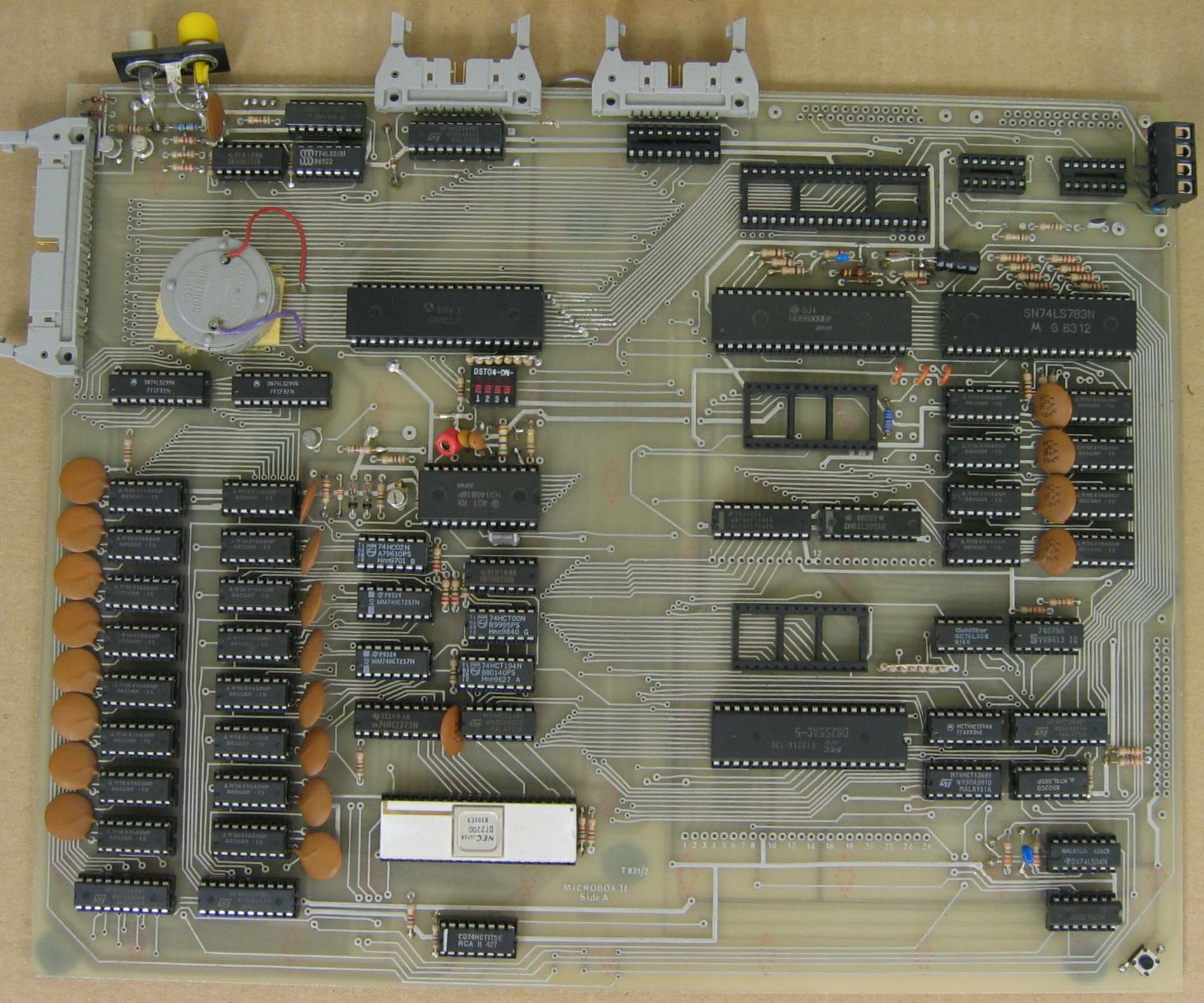
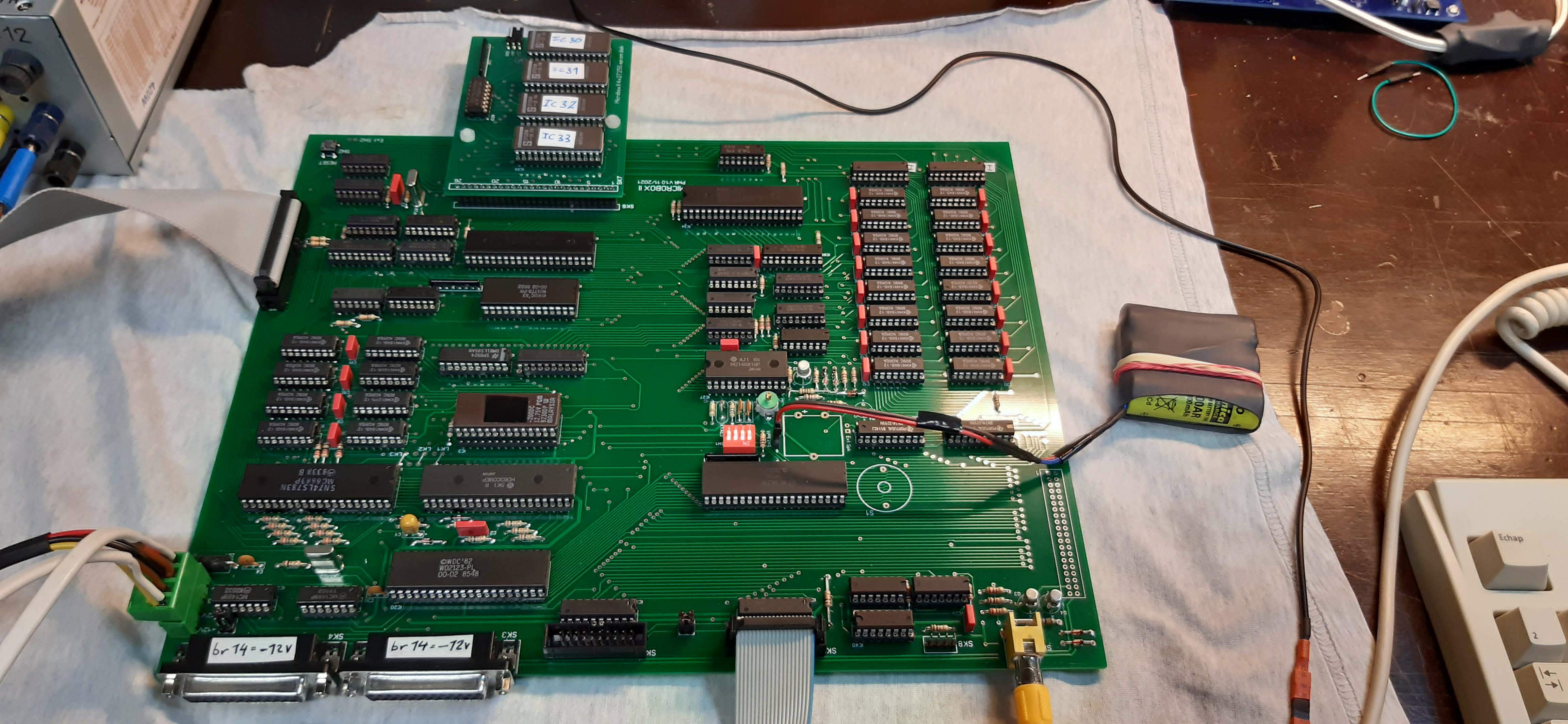
Like the TRS Color Computer and the Dragon, the Microbox uses the Motorola 6883 (74LS783) Synchronous Address Multiplexer (SAM). The CoCo and the Dragon are pretty much built according to the Application Note in the datasheet, using a 6847 to provide 16 lines of 32 characters text and up to 256 x 192 pixels in graphics mode.
Unlike the CoCo and the Dragon the Microbox II uses a NEC 7220 Graphic Display Controller instead of the 6847 CRT controller to give a maximum (monochrome) resolution of 768 x 576 -- bleeding edge 1985 technology (the Apple Macintosh debuted in February 1984 with a 512 x 342 pixel monochrome screen -- less than half the number of pixels and rave reviews).
To understand the Microbox (and for that matter the CoCo and Dragon) you need to be intensely familiar with the Motorola MC6883 / SN74LS783 SAM.
|

|
Keyboard pinouts from PCB, after the mods detailed in the User Notes, and as they are documented in the ETI article:
| pin | PCB | After mod | In ETI |
| 1 (1 inner) | IC67 pin 2 (IC19 pin 2 PA0) | D0 | |
| 2 (1 outer) | +5V | ||
| 3 (2 inner) | IC67 pin 17 (IC19 pin 3 PA1) | D1 | |
| 4 (2 outer) | GND | ||
| 5 (3 inner) | IC67 pin 4 (IC19 pin 4 PA2) | D2 | |
| 6 (3 outer) | GND | ||
| 7 (4 inner) | IC67 pin 15 (IC19 pin 5 PA3) | D3 | |
| 8 (4 outer) | GND | ||
| 9 (5 inner) | IC67 pin 6 (IC19 pin 6 PA4) | D4 | |
| 10 (5 outer) | GND | ||
| 11 (6 inner) | IC67 pin 13 (IC19 pin 7 PA5) | D5 | |
| 12 (6 outer) | GND | ||
| 13 (7 inner) | IC67 pin 8 (IC19 pin 8 PA6) | D6 | |
| 14 (7 outer) | GND | ||
| 15 (8 inner) | IC67 pin 11 (IC19 pin 9 PA7) | N/C | |
| 16 (8 outer) | GND | ||
| 17 (9 inner) | N/C | IC19 pin 40 (CA1 /STROBE) | /STROBE |
| 18 (9 outer) | GND | ||
| 19 (10 inner) | /RST | ||
| 20 (10 outer) | -12V | ||
Printer pinouts from PCB, after the mods detailed in the User Notes, and as they are documented in the ETI article:
| pin | PCB | After mod | In User Notes |
| 1 (1 inner) | IC68 pin 3 (IC19 pin 8 PA6) | D6 | |
| 2 (1 outer) | IC19 pin 40 (CA1 /STROBE) | N/C | GND |
| 3 (2 inner) | IC68 pin 18 (IC19 pin 9 PA7) | D7 | |
| 4 (2 outer) | GND | ||
| 5 (3 inner) | IC68 pin 5 (IC19 pin 6 PA4) | D4 | |
| 6 (3 outer) | GND | ||
| 7 (4 inner) | IC68 pin 16 (IC19 pin 7 PA5) | D5 | |
| 8 (4 outer) | GND | ||
| 9 (5 inner) | IC68 pin 7 (IC19 pin 4 PA2) | D2 | |
| 10 (5 outer) | GND | ||
| 11 (6 inner) | IC68 pin 14 (IC19 pin 5 PA3) | D3 | |
| 12 (6 outer) | GND | ||
| 13 (7 inner) | IC68 pin 9 (IC19 pin 2 PA0) | D0 | |
| 14 (7 outer) | GND | ||
| 15 (8 inner) | IC68 pin 12 (IC19 pin 3 PA1) | D1 | |
| 16 (8 outer) | GND | ||
| 17 (9 inner) | N/C | IC67 pin 11 (IC19 pin 9 PA7) | BUSY |
| 18 (9 outer) | GND | ||
| 19 (10 inner) | N/C | IC19 pin 19 (CB2 /STROBE) | /STROBE |
| 20 (10 outer) | GND | ||
Make of it what you will. I think the printer pin 9 inner needs to go to the conveniently supplied trace that leads to IC19 pin 18, as per the schematic.
The 16 MHz master clock is generated by a 74LS04 with two 330R resistors and a 10nF capacitor, along with a 16 MHz crystal.
Michael Evenson reported that a 7404 works as long as you replace the 10nF capacitor with a wire link (short).
The ETI article claims support for double-sided disks, and the block diagram on page 29 of the December 1985 edition shows a line "SIDE" from the PIA to the drive.
Pin 32 on the floppy drive connector on the PCB is however very much unconnected and there's no SIDE connection to the PIA in the actual schematics.
I asked David Rumball about it. Somewhere between MON09 4.23 and MON09 4.5, double-sided support was added. PB6 "Step Rate" on the PIA is repurposed, the step rate being stored in EEPROM. PB6 is routed to pin 13 on the 7407, and pin 12 of the 7407 goes to the floppy connector and also to a spare pull-up resistor.
(On my board, the same gate / pull-up combination replaces R37, which is the chip select to the 8255. This mod is documented in the User Notes).
The 74LS783 supports 128 cycle (7-bit) refresh 4164 chips only. Some chips (Texas Instruments is one example) won't work. Here's a nifty table.
Cram it with RAM. 256K Memory Upgrade!, Hot Coco, September 1985, using a 74LS785 SAM or SAMx4.
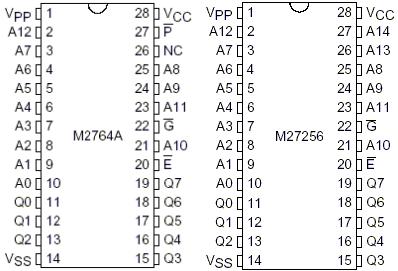
The 7220 provides 18 address lines for 256k (x16) RAM. The 4164s used by the Microbox can be changed to 41256s -- they are pin compatible, with the extra address line (one line only, because DRAM address lines are multiplexed) connected to pin 1. You'd need another LS257 chip to select between the 7220 A16 and A17 depending on the state of /ROW.
Software for this on Library Disk 40 from the UK 68 MG part of the FLEX User Group Disc Library.
The Microbox includes an Intel 8255 parallel port which interfaces to an EPROM Disc PCB. This PCB has four EPROM sockets for 27128 to 27512, giving 64 - 256 kilobytes of storage. One of the sockets can also be used to program EPROMs.
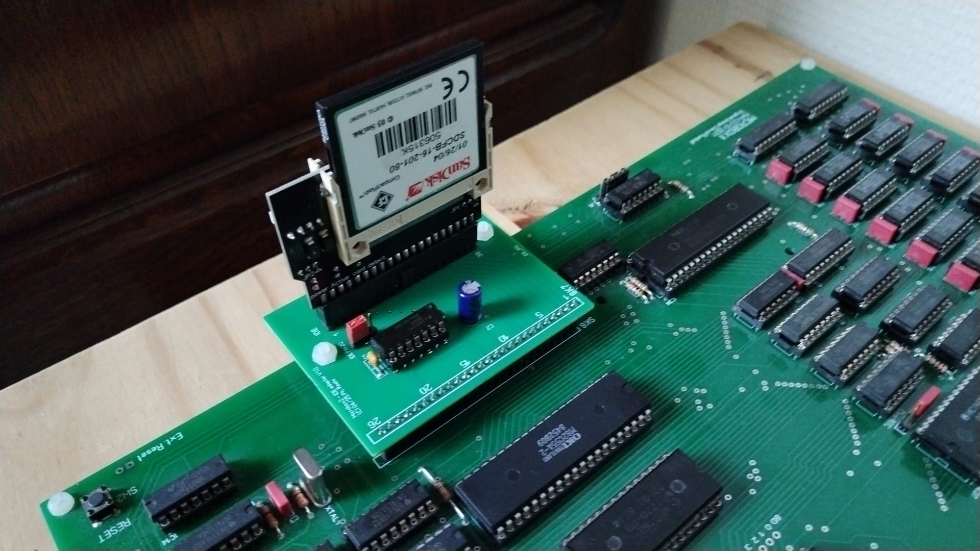
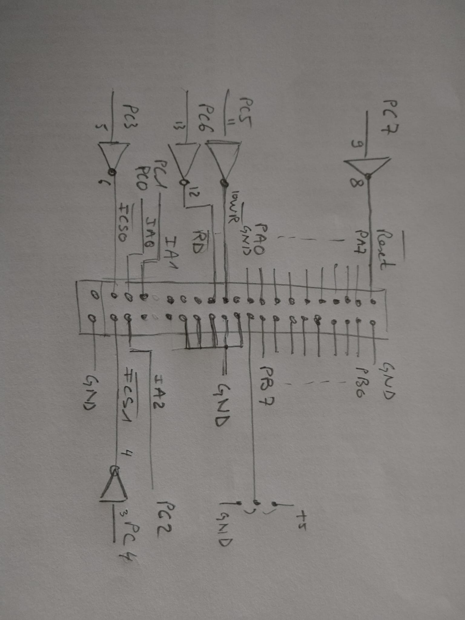
Food for thought: here's Keith Welker's archive of Peter Faasse's 8255 based IDE interface for the 6803 and here are some notes on doing the same with a 6809 and Compact Flash. The 8255 based interface is "slow", the Xilinx CPLD interface might be better -- but the Microbox already has the 8255. Also, "slow" = 25kbyte/sec, and since all of RAM is about twice that, for this application "slow" is relative.
Update Apr 2025: Philippe made a CF interface. Picture, schematic, test software, Gerbers.
It's not easy finding WD2123 information on the web.
The Timex / Sinclair FDD3000 used the WD2123 and the WD1770.
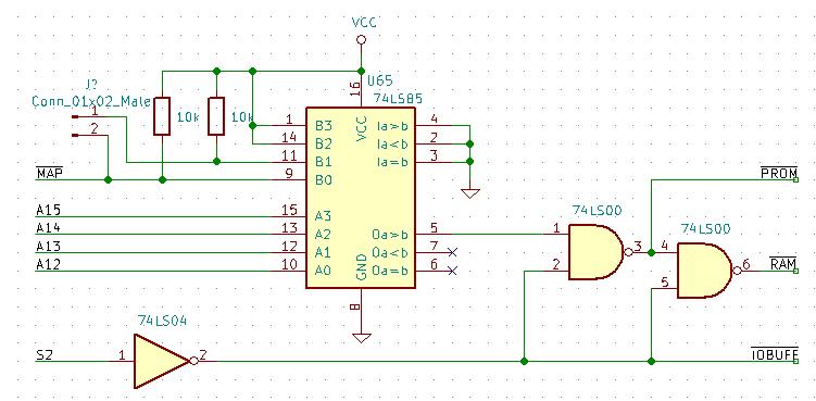
The Microbox uses a 74LS85 4-bit magnitude comparator which originally struck me as overkill, as the same job could be done with a 74LS21 4-input AND gate -- until I realised that the OR gate Dave Rumball had available is a NOR, which would require an inverter or something similar which wasn't available, so using a 74LS21 would have increased the chip count by at least one chip.
Having the 74LS85 there leads to interesting possibilities.
This is the truth table for the Microbox implementation. The output is OA=B, which when low selects RAM and when high selects ROM.
|     Comparing Inputs    | Cascading Inputs |    Outputs     | Microbox
| A3,B3 A2,B2 A1,B1 A0,B0 | IA>B  IA<B  IA=B | OA>B OA<B OA=B |
|                         |                  |                |
| A3>B3   X     X     X   |  X     X     X   |  H    L    L   | X                                    ; B3 = 1, can't happen
| A3<B3   X     X     X   |  X     X     X   |  L    H    L   | 0000 - 7FFF
| A3=B3 A2>B2   X     X   |  X     X     X   |  H    L    L   | X                                    ; B2 = 1, can't happen
| A3=B3 A2<B2   X     X   |  X     X     X   |  L    H    L   | 8000 - BFFF
| A3=B3 A2=B2 A1>B1   X   |  X     X     X   |  H    L    L   | X                                    ; B1 = 1, can't happen
| A3=B3 A2=B2 A1<B1   X   |  X     X     X   |  L    H    L   | C000 - DFFF
| A3=B3 A2=B2 A1=B1 A0>B0 |  X     X     X   |  H    L    L   | E000 - EFFF MAP=0                    ; OA>B = 1
| A3=B3 A2=B2 A1=B1 A0<B0 |  X     X     X   |  L    H    L   | X                                    ; B0 = 0, can't happen
| A3=B3 A2=B2 A1=B1 A0=B0 |  H     L     L   |  H    L    L   | X                                    ; IA>B = 0, can't happen
| A3=B3 A2=B2 A1=B1 A0=B0 |  L     H     L   |  L    H    L   | X                                    ; IA<B = 0, can't happen
| A3=B3 A2=B2 A1=B1 A0=B0 |  X     X     H   |  L    L    H   | F000 - FFFF MAP=0, E000 - FFFF MAP=1
| A3=B3 A2=B2 A1=B1 A0=B0 |  H     H     L   |  L    L    L   | X                                    ; IA=B = 1, can't happen
| A3=B3 A2=B2 A1=B1 A0=B0 |  L     L     L   |  H    H    L   | X                                    ; IA=B = 1, can't happen
But what if we connected A12-A15 to the A inputs and manipulated the B inputs instead?
|     Comparing Inputs    | Cascading Inputs |    Outputs     | B3 B2 B1 B0 | B3 B2 B1 B0 | B3 B2 B1 B0 |
| A3,B3 A2,B2 A1,B1 A0,B0 | IA>B  IA<B  IA=B | OA>B OA<B OA=B | 1  1  1  1  | 1  1  1  0  | 1  1  0  0  |
|                         |                  |                |             |             |             |
| A3>B3   X     X     X   |  X     X     X   |  H    L    L   | X           | X           | X           |
| A3<B3   X     X     X   |  X     X     X   |  L    H    L   | 0000 - 7FFF | 0000 - 7FFF | 0000 - 7FFF | OA>B = 0, RAM
| A3=B3 A2>B2   X     X   |  X     X     X   |  H    L    L   | X           | X           | X           |
| A3=B3 A2<B2   X     X   |  X     X     X   |  L    H    L   | 8000 - BFFF | 8000 - BFFF | 8000 - BFFF | OA>B = 0, RAM
| A3=B3 A2=B2 A1>B1   X   |  X     X     X   |  H    L    L   | X           | X           | E000 - FFFF | OA>B = 1, ROM
| A3=B3 A2=B2 A1<B1   X   |  X     X     X   |  L    H    L   | C000 - DFFF | C000 - DFFF | X           | OA>B = 0, RAM
| A3=B3 A2=B2 A1=B1 A0>B0 |  X     X     X   |  H    L    L   | X           | F000 - FFFF | C000 - DFFF | OA>B = 1, ROM
| A3=B3 A2=B2 A1=B1 A0<B0 |  X     X     X   |  L    H    L   | E000 - EFFF | X           | X           | OA>B = 0, RAM
| A3=B3 A2=B2 A1=B1 A0=B0 |  H     L     L   |  H    L    L   | X           | X           | X           | IA>B  IA<B  IA=B all low, can't happen
| A3=B3 A2=B2 A1=B1 A0=B0 |  L     H     L   |  L    H    L   | X           | X           | X           | IA>B  IA<B  IA=B all low, can't happen
| A3=B3 A2=B2 A1=B1 A0=B0 |  X     X     H   |  L    L    H   | X           | X           | X           | IA>B  IA<B  IA=B all low, can't happen
| A3=B3 A2=B2 A1=B1 A0=B0 |  H     H     L   |  L    L    L   | X           | X           | X           | IA>B  IA<B  IA=B all low, can't happen
| A3=B3 A2=B2 A1=B1 A0=B0 |  L     L     L   |  H    H    L   | F000 - FFFF | E000 - EFFF | C000 - CFFF | OA>B = 1, ROM
So with two MAP inputs (B0 and B1) and using the OA>B output, we can have EPROM from F000-FFFF (4k), or from E000-FFFF (8k), or from C000-FFFF (16k). Of course this needs a 27C128 or 27C256 EPROM and a few board mods but hey -- it means you can (for example) run Jeff Tranter's combined firmware which is ASSIST09, a disassembler, a tracer, and Microsoft (CoCo) BASIC. Whatever. Basically, you can build a ROM which has all the core stuff in F000-FFFF, the graphics support in E000-EFFF, and BASIC from C000-DFFF. Or something like that.
| 1767 hits since 2003-09-29. | Back to Wouter's 6809 Page | (This page last modified 2025-07-10) |