Electronics

Mind Bender

So I recently retrieved my Argonaut 505 Amateur Radio Transceiver from storage. Turned it on, no hiss from the speaker. That’s… unusual, points to a dead audio amplifier.

Geek line, do not cross. Geek line, do not cross. (TLDR: I solved the problem)

Continue reading…

Avo Model 9 Mk II

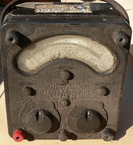
My parents bought this Avometer for me at a boot sale when I was most likely still in primary school. It didn’t work, of course. But it’s a neat piece of kit.

I remembered about it again the other day and went to find it in the attic where I do quite a bit of stowing.

A few decades worth of dirt.

Some cleaning and some googling and…

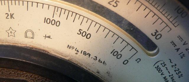
Hey! It’s a year older than I am (366 = March 1966).

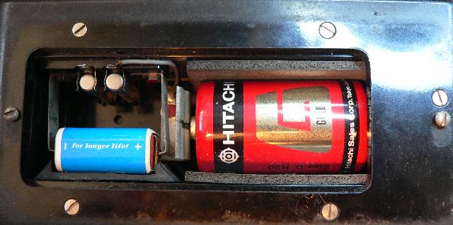
I’ve never even seen one of the 15V batteries for sale anywhere, so these batteries have been in here since before I got the meter. And most of the time I’ve had it was spent in a hot attic. The batteries are flat, of course, but I would have expected things to look a whole lot worse.

Now I distinctly remember that I tried to find out what’s wrong with this meter, and at the time I concluded that the movement was not working. Well, it turns out that there’s nothing wrong with the movement. This is great news. Anything else is easier to fix than a d’Arsonval movement.

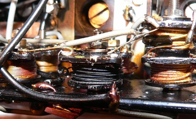
Here’s the damage. This is the 42.2 ohm resistor between the 10mA and 100mA taps on the DC switch (see the schematic at the end of the user manual) and I would say that it’s maximum power rating was exceeded…

I will see whether I can find or make or devise a replacement*, and I’ll clean up the outside.

Please, if you have one of these, be nice to it, don’t gut the insides like this poepol did.

* Believe it or not, 42.2 Ohm is an E96 value, but I might need a higher wattage and I’d probably end up putting ten 422 Ohm 1% resistors in parallel. Edit: Six 470 ohm, six 560 ohm, and one 4k7 in parallel makes 42.2065 which is good enough for me.

(Edit: link to balancing the movement)

Repairs

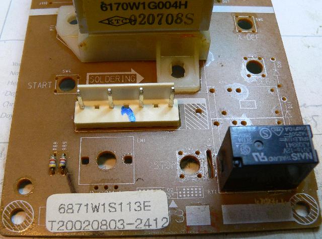
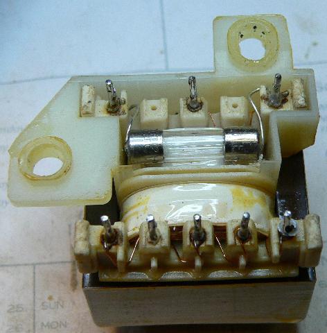
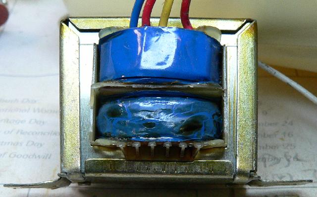
This is the 6871W1S113E control board from our LG MG-604W microwave. The transformer primary went open circuit when the supply hit 300V or thereabouts. I know that these things often incorporate some kind of protection circuitry, so I desoldered the transformer.

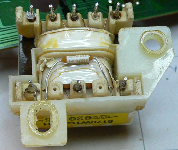
Sure enough, it’s a 1A 130C fuse.

Fixed (yea, this solution doesn’t have thermal protection. I can live with it).

Of course, now that I know the layout I know that one can add a fuse or a jumper to the PCB without having to desolder the transformer. Again, you’ll lose thermal protection.

The transformer primary is between the left and middle pins, and the fuse runs from the righthand pin to the lefthand pin.

I was not so lucky with the Sakyno SK-1000 clock radio. In this case the transformer primary was the protection device, and the magic smoke leaked out.

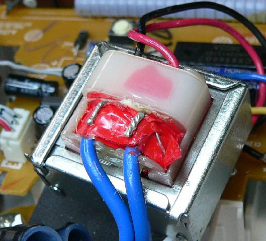
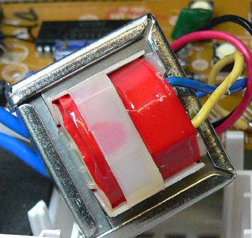
The Philips AJ3121 clock radio transformer has a fuse as well, the wire leading down on the right hand side goes over to the other side, where there’s a square  125C thermal fuse wrapped up against the winding.

It’s at the left hand side under the red tape under the plastic.

Unfortunately I stuffed it up, I jiggled the wire too much and the primary winding, which is cat-hair-thin, broke off from the fuse lead. I tried resoldering it but it’s just too finicky.

So we bought two new clock radios. But at least the microwave works.

Mystery object

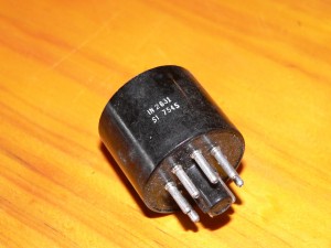
Long story short, my Father in Law ended up with Marconi Instruments Ltd No 1 Mark II* signal generator and a dozen boxes of assorted parts. I’d guess it was an Elmer‘s Junkbox.

Can’t find any information on this on the web. Marked IN 2631 and SI 7545, my best guess is that it might be a solid-state rectifier intended to replace a vacuum tube.

So if Google brings you here and you know more… that’s what the comments are for.

Edit: It’s a ONE N 2631.