ZS1KE

Kids today…

I have a… idunno, I guess I’m (one of) his Elmer(s) but I don’t know what that makes him. PFY, maybe. Told him I’d drop some stuff off for him to use to try to revive the PLL on an Icom IC-240 (the TC5080 had snuffed it).

Anywayz, so this Whatsapp convo goes down:

(Yea, I wind him up. I feel it’s my duty).

Westinghouse NT-33 Antenna Ammeter

From my stash of interesting stuff. I know very little about measuring antenna current, I’ve never seen it covered in a Radio Amateur Handbook or the like. Not even my 1948 edition.

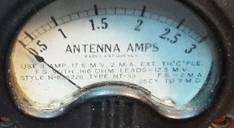
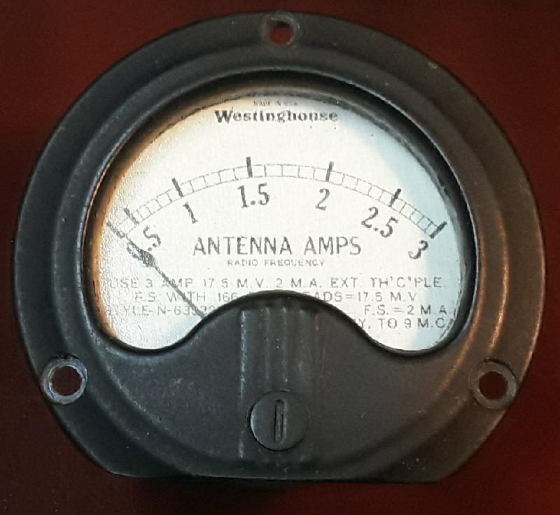
The meter face (note the non-glare glass) reads “USE 3 AMP 17.5 M.V. 2 M.A. EXT TH’C’PLE. F.S. WITH .166 OHM LEADS = 17.5 M.V. STYLE N-635226 TYPE NT-33 FS = 2 M.A. 25 CY TO 9 M.C.

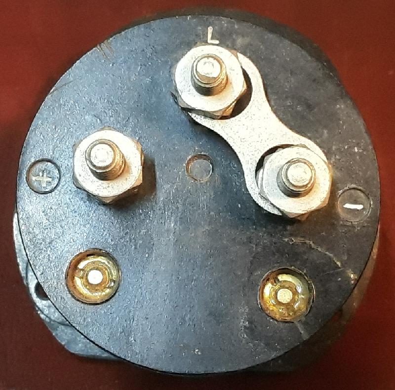
It has three terminals and I have no idea what “L” means.

Turns out “L” is connected to the back of the meter face. Still don’t know what it stands for.

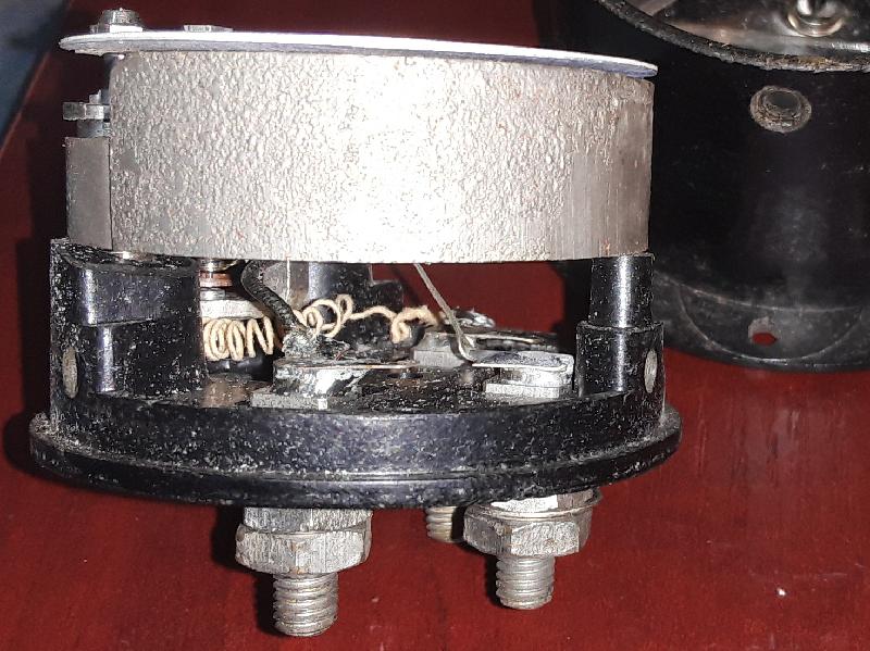
Anyway, it’s a non-linearly calibrated d’Arsonval movement with a (measured) internal resistance of 8.5 ohm and an FSD of 2mA. 17.5mV over 8.75 ohm is 2mA, so depending on whether the 0.166 ohm lead resistance is for one or both wires, the internal resistance should be 8.58 ohm or 8.42 ohm so yea, the complete meter spec is written on the meter face if you know what to look for.

It should look good in some retro kit, even if I have to interface a PIC to the back of it to get the calibration right.

SWR Meter rebuild

From a bunch of stuff some other ham wanted to throw away, this ex-SWR meter.

Stripped

I have no idea why the Dreaded Previous Owner stripped it down to this state. The meter movement is fine, 950-ish mV over a 4k7 resistor gives FSD, so it’s a 200uA unit.

inside

The detector components are still in place, and it looks very similar to the Micronta 21-520A except that there’s only one meter. There’s also a little bobbin on the side for an antenna, presumably to make it into a Field-Strength Meter, but that’s a gimmick and won’t happen.

NewSwitches

The junkbox yielded two switches of the right type and size (one selects Power / SWR, and in SWR mode the other selects Forward / Reverse). There will also be a pot to set FSD in Forward mode after which the Reverse mode should give the SWR. Give or take. Don’t expect a lot from meters like this.

Fast forward a bit and we have

IMG_0070r

IMG_0068r

Don’t ask me what used to live in those two extra holes. This setup works for me, for the price of a few junkbox parts and some time.


This… is stupid

(IMO, of course. And Geek Alert)

MFJ-949E

This is the switch and tuner schematic for an MFJ-949E Versa Tuner II. Great little unit, with a built-in dummy load. It has a switch that selects the dummy load, then the three antenna connectors in pass-through mode, then the three antenna connectors through the matching network, and then the dummy load again… through the matching network.

Which means that if you want to tune into the dummy load, you have to use the setting all the way to the left, or you have to adjust the tuner to match the dummy load to the rig, using the switch setting on the right.

Now why would you need to match a 50 ohm dummy load to your rig? Insane. The dummy load switch setting on the right should connect straight to the dummy load, not via the tuner.

I have a soldering iron, I can fix it.

New life for your FT-290R

I mentioned previously that I figured out how to make a new display for an FT-x90R. My own rig is still in pieces ‘cos I’m not quite happy with the software yet (or actually, with my reverse engineering of the display protocol, but it’s the same thing in the end).

But Dave ZS5DF wanted his rig fixed so I fitted a new display, even though it doesn’t have the F key “P” priority display function in firmware yet.

P1130871r

Two filament bulbs, because the replacement display needs light from the right-hand side and the S meter is on the left-hand side.

P1130882r

Component cost is close to R500 which almost puts it in good-money-after-bad territory but I like these little radios.

No. No, I wasn’t born yesterday.

Thank you for asking.

Background: I think I found a way to fix a broken display on my Yeasu FT-290R 2m all-mode radio. A broken display on these things is common, and displays are very much NLA. The FT-290 (2m), FT-690 (6m) and FT-790 (70cm) are all pretty much identical except for the RF bits, so a fix for one is a fix for all.

So I advertised on swop shop, looking for an “FT-290R / FT-690R / FT-790R”.

Hello   Wouter ,

Thanks for the mail. I have the requested FT-290R / FT-690R / FT-790R
in an excellent condition  I will be shipping via FedEx courier on a 3
working days delivery and will accept payment via Western Union or
Money Gram
.

Location: USA

What’s your complete shipping address?

First and foremost before proceeding with transaction we can only
accept payment via western union if you are satisfied with that kindly
get back to me.

Maybe I should ask for a photograph of this “FT-290R / FT-690R / FT-790R”.


Boat Anchor

Well, almost. In Ham Speak, a boat anchor is an old, large, probably obsolete piece of radio equipment. I have more than one.

However:

The Heathkit HW-32 only qualifies if you have a tiny boat. At about 30cm wide and 15cm high, it’s actually quite small for a 14 valve transceiver rated for 200W PEP output. OK, it only does this on a single band, 20m in this case (the HW-12 and HW-22 covers 80m and 40m respectively).

Frequency coverage is 14.2 to 14.35 MHz, for mobile SSB operation. There’s no provision for CW and no coverage of the CW portion of the band.

At 5 1/2 kilos, it’s also too light to be a boat anchor — but that’s because it doesn’t have a built-in power supply. You need to supply 800V DC, 250V DC, and -130V DC bias, as well as 12V for the filaments.

We’ve come a long long way in 50 years.