A friend gave me two “Spectrum” VHF handhelds. No model number on the radios, the battery packs are “Model N91A”. AI assisted image seach came up with “Kukjae PC-4312”. For what _that_’s worth.
Anyway, I figured these would make good APRS radios for some of my vehicles, provided I could move them to 144.800.
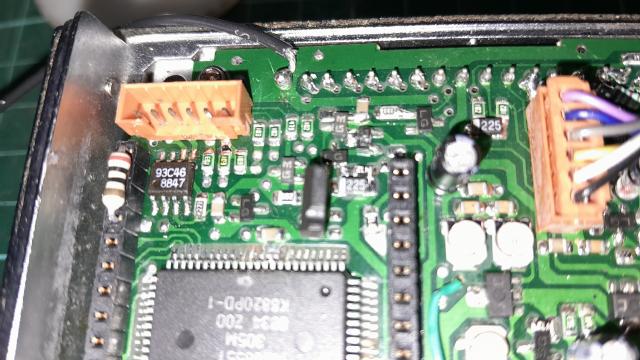
Opening it up revealed a 93C46 EEPROM connected to a header and from there via resistors to the MB88551 4 bit mask ROM CPU. Obviously the idea is to program the EEPROM while the CPU is not looking, while the resistors prevent a clash. Some more digging revealed that the 93C46 is actually a rotated package, just to make life more interesting I guess.
Anyway. Broke out PulseView, hung it on the wires, turned the radio on, changed channels. The Microwire decoder worked fine, but the 93C46 decoder got confused, so I had to read the bits.
On startup (channel switch on channel 9):
     543210 0123456789abcdef
1 10 001000 0000000000000000 0x08
1 11 111110 0101101110110010 0x5BB2

1 10 011000 0000000000000000 0x18
1 11 111110 0101100101101010 0x596A

1 10 101000 0000000000000000 0x28
1 11 111110 0000000000000000 0x0000

1 10 110000 0000000000000000 0x30
1 11 111110 0010100100000000 0x2900

1 10 110001 1111111111111111 0x31
1 11 111110 1011101110111011 0xBBBB

1 10 110010 0000000000000000 0x32
1 11 111110 1011101110111011 0xBBBB

1 10 010000 0000000000000000 0x10
1 11 111110 0101100101100100 0x5964

1 10 100000 0000000000000000 0x20
1 11 111110 0000000000000000 0x0000
Let me explain. The top line is the data to the EEPROM, “10” is read, then there’s a 6-bit address. The zeros or ones after that don’t matter, this is where the data gets clocked out on the second line. So it’s reading location 0x08, 0x18, 0x28, etc., all in 16-bit mode.
Change to channel 9:
1 10 001001 1111111111111111 0x09
1 11 111110 0101101110101010 0x5BAA

1 10 011001 1111111111111111 0x19
1 11 111110 0101100101100010 0x5962

1 10 101001 1111111111111111 0x29
1 11 111110 0000000000000000 0x0000
Same thing, reading locations 0x09, 0x19, ox29. First guess: receive PLL parameters, transmit PLL parameters, unknown (but zero for all channels) parameters (call ’em “flags” for now).
On startup, it reads the selected channel parameters and then a further 5 parameters. Two of these are the receive VCO frequency and flags for channel 1, maybe it’s like a priority channel. The other three, your guess is as good as mine.
Now to find out what frequencies these parameters map to. Transmit is easy, dummy load and frequency counter. Receive was more tricky, I had to disassemble the sandwich to get to a point on the VCO, soldered a wire there, re-assembled, frequency counter — and found that it was the transmit frequency. Repeated the whole process, found the receive oscillator. Put it all in a spreadsheet, started looking at the data, and found that one channel had the two frequencies separated by 10.7MHz. Ha! This channel is simplex. The other channels were all 7.05MHz split repeater channels.
So now I knew that 0x5D50 and 0x56A0 both mapped to 149.300, with a 10.7MHz difference. The difference is 0x6B0, decimal 1712, and 10.7MHz / 1712 is 6.25kHz, yea I might actually be on to something.
Some more spreadsheeting and the answer is, the parameter in hex is the VCO frequency in 6.25kHz quanta. Also, the first 16 parameters are the transmit frequencies and the next 16 parameters are the receive VCO frequencies.
OK, that was the easy part.
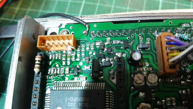
The EEPROM came out easily enough, then I had to solder it to a socket (just like last time, but rotated), stick it in my EEPROM programmer, read the data, edit the data, write the EEPROM, unsolder it from the socket and put it back on the PCB.
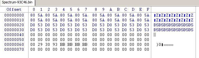
0x5A80 and 0x53D0 are the magic numbers I came up with to get to 144.800. And hey, it seems to work.