Prepping
Prepping (i.e. making sure you have enough essential stuff stored away to tide you through a difficult time) is always a good idea. Now is a good time to start.
“Now” is an especially good time to start prepping for Day Zero. Here are some good ideas, except go light on the rice and dried beans (you need water to cook those) and buy water, not empty containers.
Successful prepping revolves around buying more of the kind of stuff you’d buy anyway, and then rotating it. Day Zero is not going to go full-on Zombie Apocalypse on us (we all hope) but the supply chain might be slow due to people having to queue for water, rather than being at work. If you also have to queue for water, and maybe go to work*, taking the time out to go to the shop will be a luxury. So shop now.
But don’t go out and buy a ton of freeze-dried Bear Grylls stuff you’ll end up never using and throwing away, just get extra stock of the tinned stuff you normally get, stick some extra chicken or mince or steaks if you can afford it in the freezer, that kind of stuff.
Remember to keep your plastic grocery bags, you’re going to need them :-/
Also, waterless hand cleaner and bleach. Paper plates might not be a bad idea either. A fellow student, back in the early nineties, kept his plate in his fridge so he only had to wash it once a week. He was just lazy, but if water’s scarce, it could work.
Start thinking about food recipes that need little water. I made this one the other night, it’s pretty damn good.
And have a Plan B. Always have a Plan B.
*Although how one can be expected to work when the toilets don’t flush is beyond me. Note that this also applies to the staff at your friendly local grocery store. Which brings us back to the point — shop now.
A Neglected Anniversary
The 28th of December gets no respect. It’s just another day in the week most people take off to go to the beach.
But 100 years ago people sat up and noticed. Specifically, they noticed an article in the New York Evening Mail.
The Rise of the Bathtub
The first bathtub in the United States was installed in Cincinnati December 20, 1842, by Adam Thompson. It was made of mahogany and lined with sheet lead. At a Christmas party he exhibited and explained it and four guests later took a plunge. The next day the Cincinnati paper devoted many columns to the new invention and it gave rise to violent controversy.
Some papers designated it as an epicurian luxury, other called it undemocratic, as it lacked simplicity in its surroundings. Medical authorities attacked it as dangerous to health.
The controversy reached other cities, and in more than one place medical opposition was reflected in legislation. In 1843 the Philadelphia Common Council considered an ordinance prohibiting bathing between November 1 and March 15, and this ordinance failed of passage by but two votes.
During the same year the Legislature of Virginia laid a tax of $30 a year on all bathtubs that might be set up. In Hartford, Providence, Charleston and Wilmington special and very heavy water rates were laid on persons who had bathtubs. Boston in 1845 made bathing unlawful except on medical advice, but the ordinance was never enforced and in 1862 it was repealed.
President Millard Fillmore gave the bathtub recognition and respectability. While Vice President he visited Cincinnati in 1850 on a stumping tour and inspected the original bathtub and used it. Experiencing no ill effects he became an ardent advocate, and on becoming President he had a tub installed in the White House. The Secretary of War invited bids for the installation. This tub continued to be the one in use until the first Cleveland Administration.
And it’s been bouncing around the world and the internet since.
Happy Birthday Dear Jesus
It’s 8 000 words long, short for a story, maybe a bit long if you’re of the twitter generation, but well worth the read.
1956. Science Fiction authors are sometimes true visionaries.
Slovenia 2017 – Going home
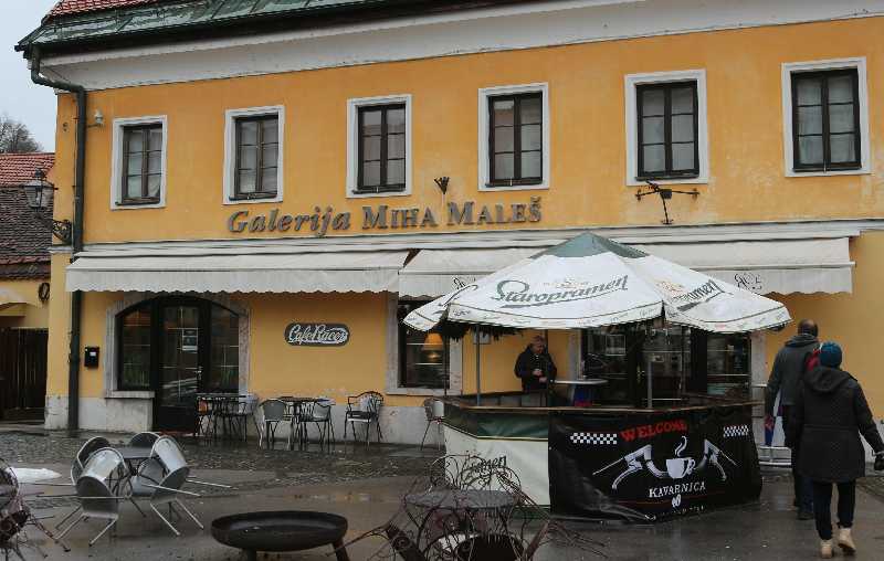
We had all day to get to the Malpense airport outside Milan so we were in no great hurry. Turned off the highway and had coffee at Cafe Racer in Kamnik.
From there we went to see what Lake Bled looks like. It was raining, I don’t even have half decent pictures — but it looks like it can be stunning in summer. Which is probably why Bled features on the front page of so many travel guides to Slovenia.
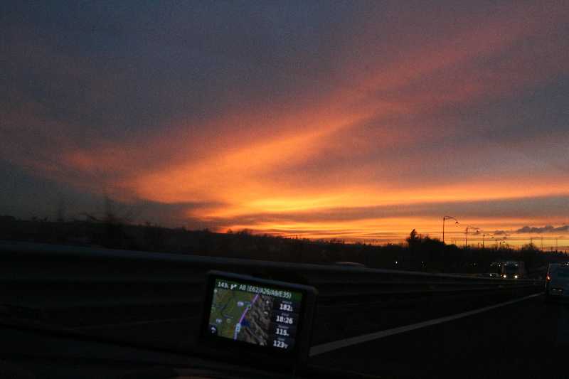
It was around this point that we put Malpense into the GPS and realised that we didn’t have all day, and that we would have to put foot to get to the airport in time to catch our flight.
So Pieter put foot.
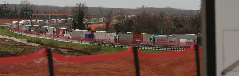
This is not what you want to see if you are trying to put foot. 82 kilometers before Venice, we were stuck here for maybe 40 minutes.
We ended up giving them the car with an empty tank, and there’s a penalty for that but… we made the flight. Well, we managed to book in our baggage in time, that’s the important thing. Then we got caught in a free-for-all in the passports queue, and when we finally boarded the plane got delayed for an hour but… we made the flight*.

Addis Ababa is not known for their tolerance of airlines other than Ethiopian. Because of being late, we basically walked in the one door and our the other without going through security (good) or duty free (bad). And then we sat on a mostly empty plane watching people arrive in dribs and drabs and hoping that the last group would be the last group so we could have plenty space on the plane. We ended up with plenty space on the plane. I slept through most of the flight. That’s how I roll.
- You have to be at the airport two hours before the flight. Unless you book in electronically, then it’s an hour. We had three cellphones and one iPad, and airtime enough to find the website (not ethiopianairlines.com) and book in and email the boarding passes to Pieter’s account. He didn’t have airtime to download the boarding passes but the airport supposedly had free wifi. Didn’t get that working but didn’t get hassled either so that was all good. Sheesh, I remember the days when your tickets came printed in quadruplicate in a book.
Slovenia 2017 – Murska Sobota again
So on Monday we drove out to Murska Sobota again.
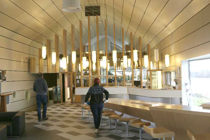
Our appointment was for one, so we dawdled around a bit, visited the Marof winery (winemaker, Pieter’s friend Uroš). Impressive place. Good wine, too.

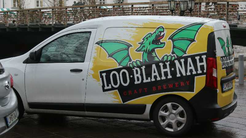
This little Land-Rover lives with his mate the Renault and a bunch of other junk at 5 Bogojina on the road to Dobrovnik.
Had lunch at the Gostilna Pri Lujzi in Dobrovnik, then kept our appointment with the lawyers, signed a bunch of papers, stuck some money in a bank, had some coffee, and drove back to Maribor, where it was pretty much pitch dark already. Walked across the bridge and went shopping at the InterSPAR, cheese and cold meat and wine and beer, called it supper.
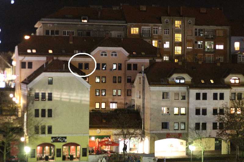
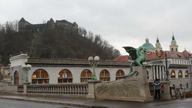
View from the bridge, that’s the windows of the place we stayed in.
Slovenia 2017 – Weekend in Graz
As mentioned previously, Tanya insisted on coming along on this trip because she has a scrapbooking friend in Graz.
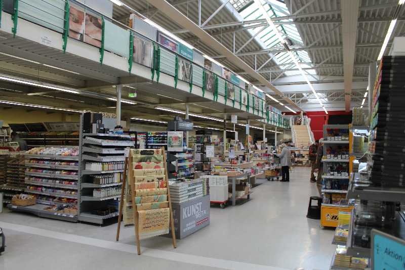
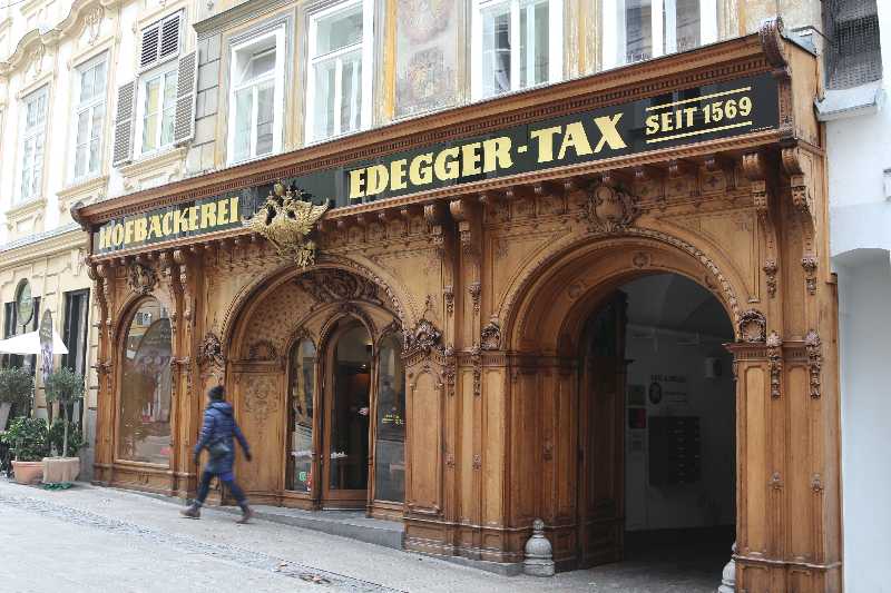
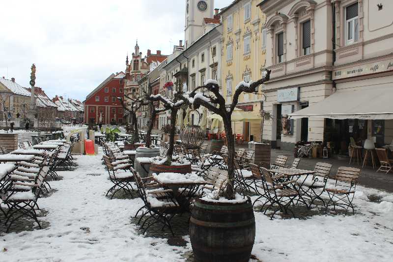
So the first stop was a rather large arts crafts and scrapbooking place, after which we found parking close to the Graz Cathedral and walked down Hofgasse and Sporgasse into the centre of town — which was packed.
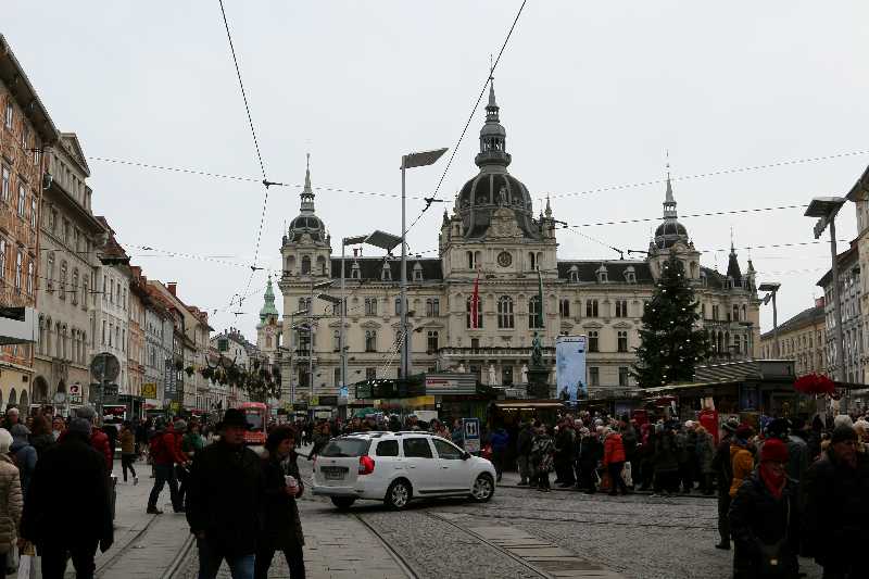
The weather wasn’t so great for photographs.
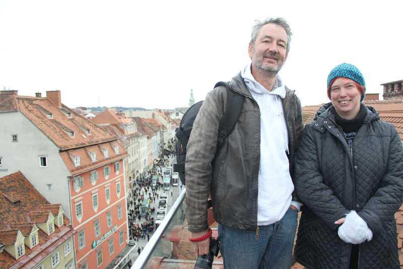
This is the view from Freiblick, a rooftop cafe above Kastner & Öhler. It was cold. The wind chill up there was bracing. There were people sitting outside having coffee and stuff. I suppose you get used to the cold.
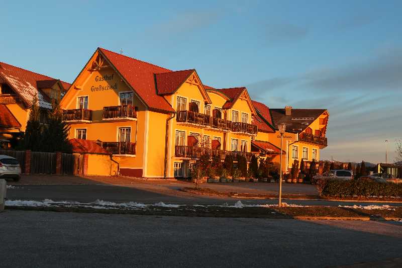
Our hosts had booked us into the Gasthof Grosschedl zum Kramerwirt which is close to where they stay, outside Graz. Slightly upmarket from what I normally pick, very nice of course.
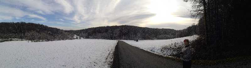
… and back to Maribor, where it had snowed while we were in Austria.

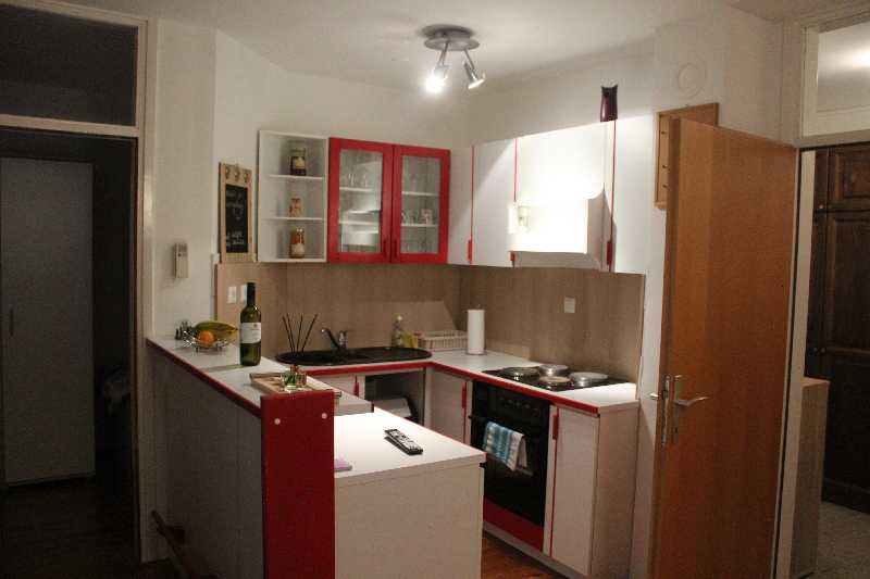
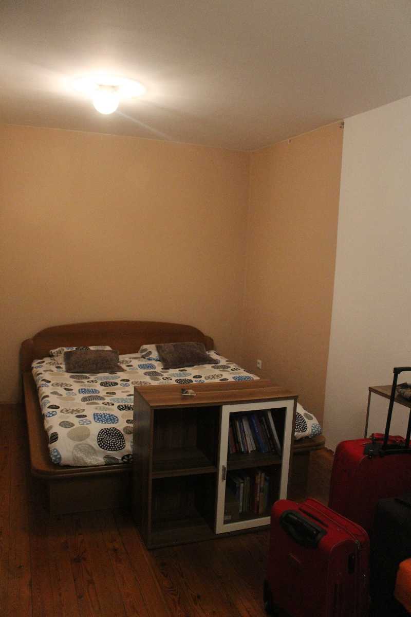
Pieter found us a very nice place just around the corner from the main square, on the river. This is the view from there, facing south. The building on the left is the Maribor U Faculty of Medicine. We had the place to ourself — Pieter was still booked into his place for one night.
Slovenia 2017 – Ljubljana and Maribor
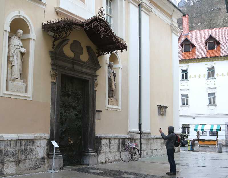
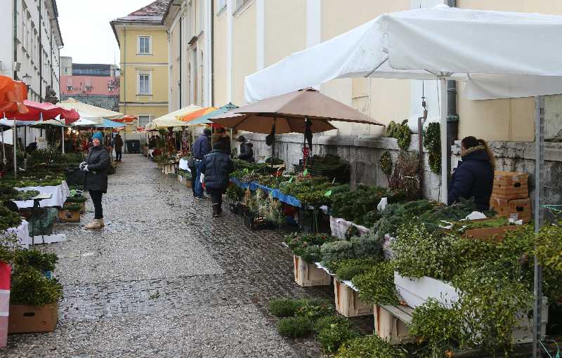
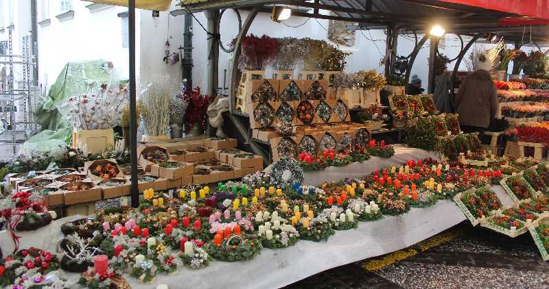
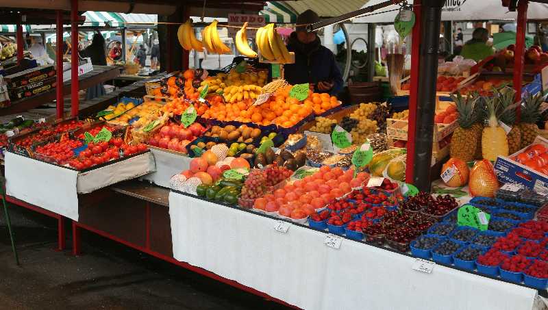
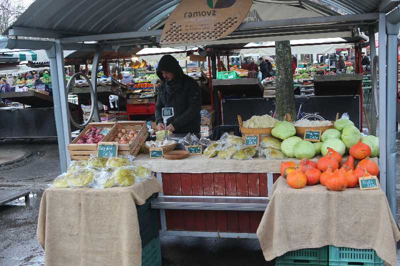
Friday is market day in Ljubljana. It’s not huge in winter, it’s apparently stunning in summer. We went to have a look anyway.
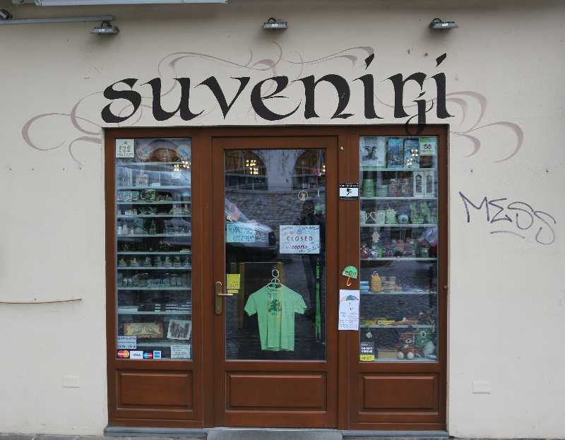
… Novelti, Paarti Triicks (what?).
And then we were off to Maribor.
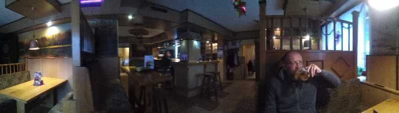
Got there, went looking for free wifi. You know the story.
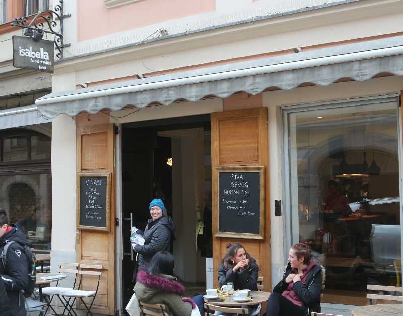
The Kavarna Isabella looked good — it’s hard to see at this resolution but the top Vinarji is Marof — more on this later. Pieter contacted his landlord, walked over the bridge to go find the place (walking being easier than finding parking), came back and we went to drop him off.
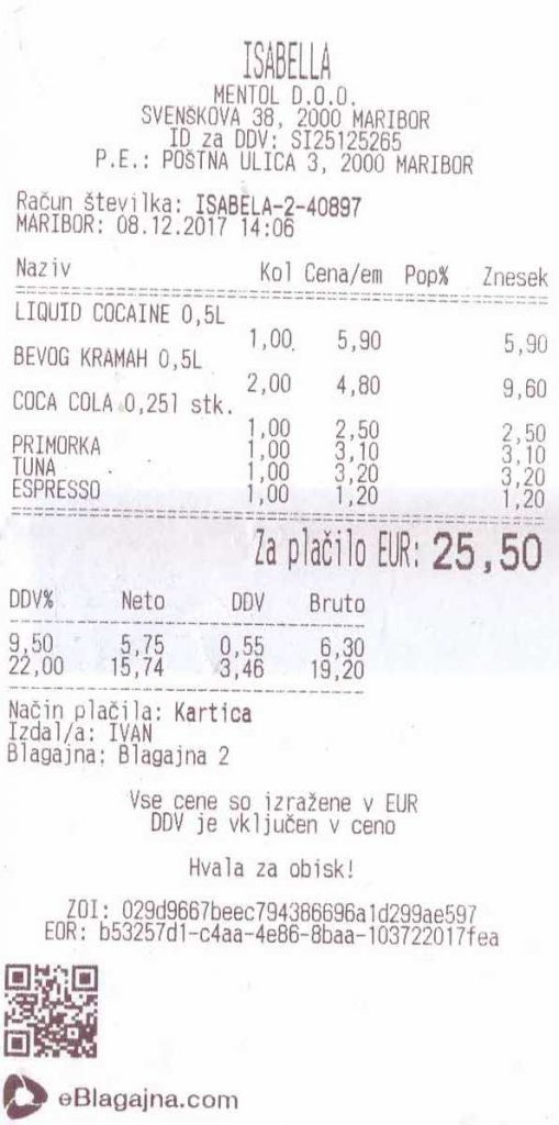
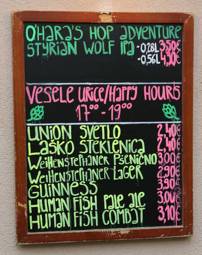
(Liquid Cocaine is IPA — beer from Hungary. Pretty good beer too, but King’s Blockhouse is better).
Then we took the car and went off to visit Tanya’s friend Irit in Graz for the weekend, leaving Pieter stranded in Maribeer on a craft beer weekend with nothing to do but hang out with his friend Uroš and partake of the fruits of the country. Shame.
Slovenia 2017 – Murska Sobota
So this is what we actually came for — go to Murska Sobota, sign some papers, do some stuff, sign some more papers, then wait. Maybe if something happens, sign some more papers on Monday, then go home.
Got to the lawyer’s offices in Murska Sobota and they were nowhere near ready for us. Still had to arrange a translator and all kinds of stuff. Arranged to go back there on Monday, went for some sightseeing towards Ljutomer. It was a rainy day so we didn’t take many photographs.
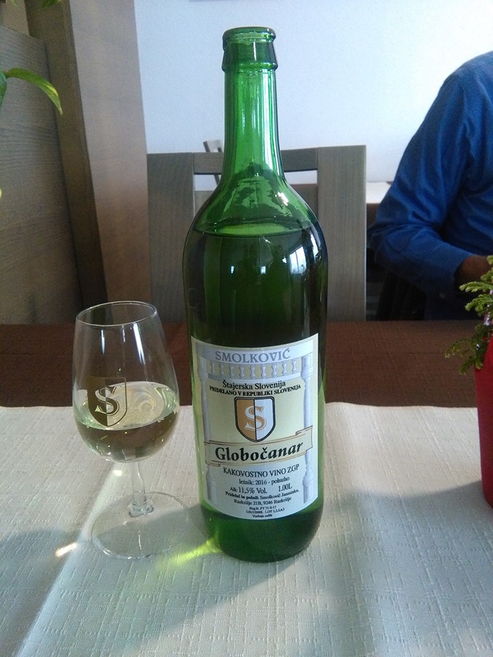
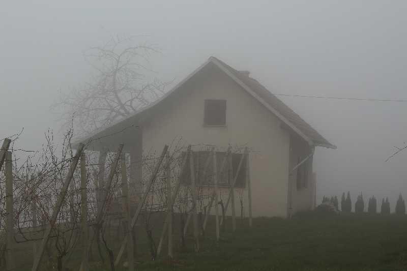
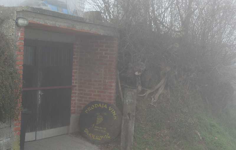
Ended up at the Smolkovic* place for lunch. Yes, Pieter knows the people, he’s been there before (fairly obvious that they’re our kind of people, if they put wine in litre bottles with crown caps). Met Primož, Robert was out somewhere.
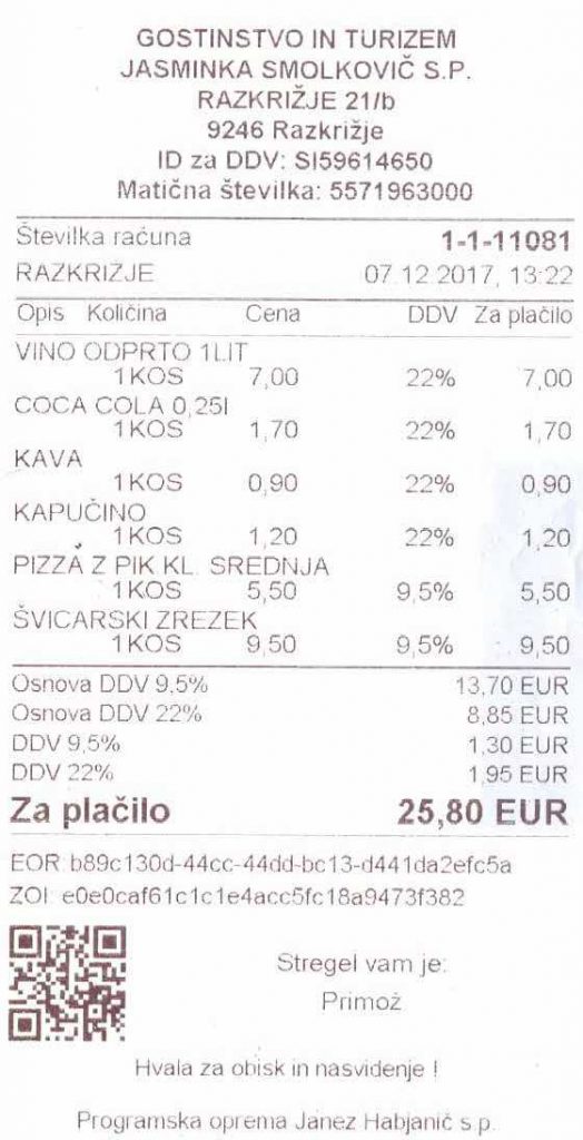
Švicarski zrezek is Swiss steak. Pizza is pizza everywhere. There was enough to go around.
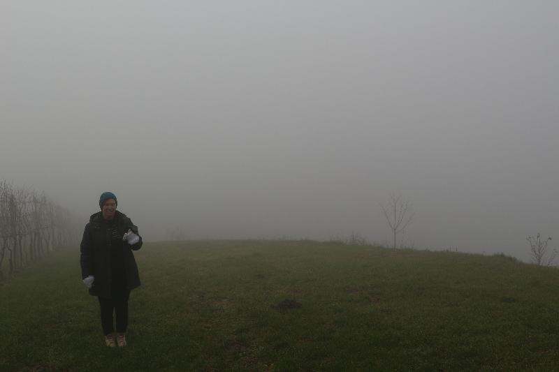
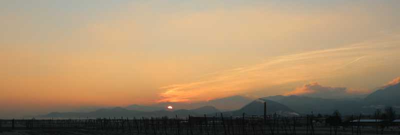
Went sightseeing. Look at that view.
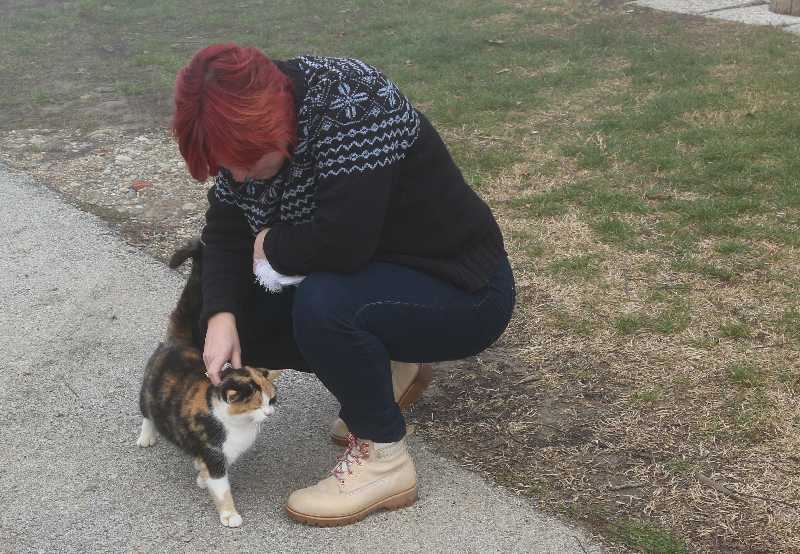
Of course Tanya found a friendly cat.
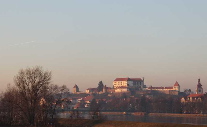
Drove back via Ptuj. Like many towns it has a castle up on a hill. Golden hour, half past three in the afternoon. The days are not long in winter.
Meanwhile we had gone shopping at the Tuš. Bought wine. More than enough wine… I thought. But first we went for a couple of beers. After that, Pieter reheated what was left of the mixed grill, and we started tasting wine.
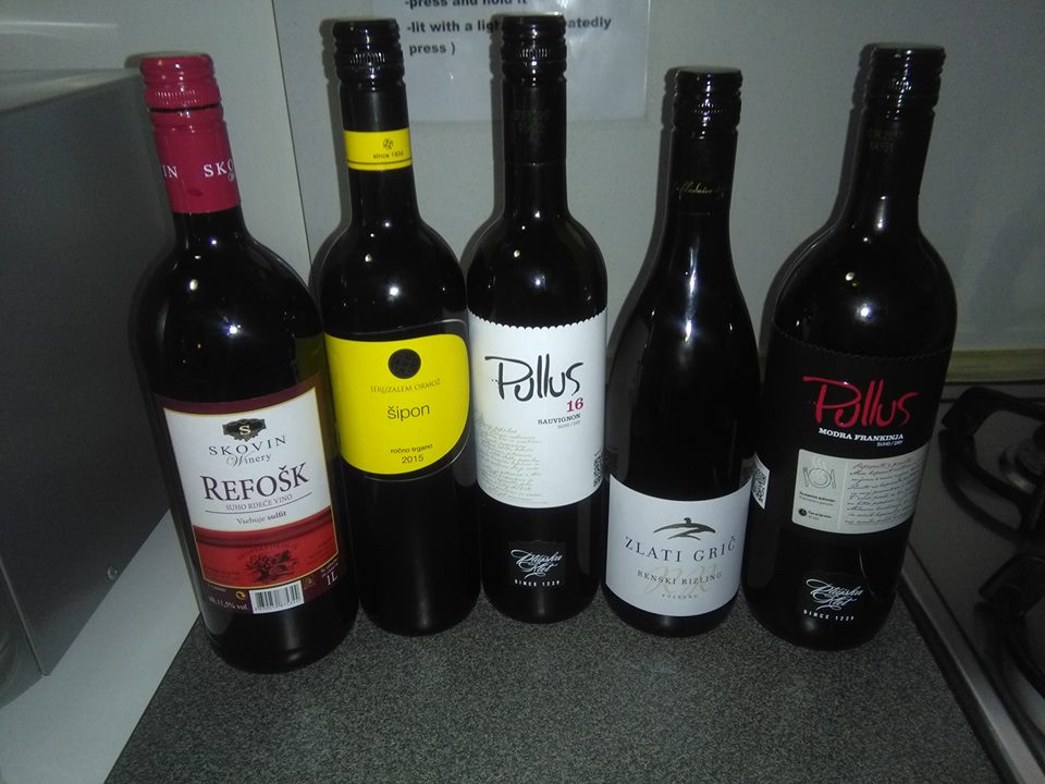
These are the corpses, photo taken the next morning. OK, the Refošk was not empty, the others… were. Three of us. Tanya complained that Pieter had snored all night long. He probably did, Idunno, I was fast asleep.
- It’s a c caron. “č”. The moment WordPress saves the file, it converts it from “&ccaron” to the single character, which it then saves, and then somehow it becomes “?”. Don’t ask me why. S caron š and z caron ž works just fine.