Electronics

Meriva Indicator Relay

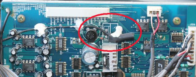
So the kid complains that the indicator lights on the one side of the Opel / Vauxhall Meriva stays on all the time. This is a well known problem, there’s a dual relay and the contacts burn and stick.

So I open the box up and give her a stick and show her where to beat the relay into submission lightly tap the relay with a stick to make the stuck contact release. Problem being that once that’s done, if you then lock the car the indicators flash and guess what? Yup, bloody thing sticks again.

Google tells me you can get a new one for under 15 Sterling, which at the current exchange rate is around three hundred rands if you hurry (the rand seems to be heading south a bit faster than normal right now). But there’s shipping on top of that and it takes a while so let’s see…

<ring> <ring> “Opel spare parts, how may I help you?”

Me: “Yea hi I need an indicator relay for a Meriva,  part number 09 134 880”

Them: “Yes sir, we have those in stock, one thousand seven hundred and twenty rands”

Me: “You Have Got To Be Shi, I mean, Surely that cannot be the case my good man?”

Them: “Oh yes sorry, my mistake, make that one thousand seven hundred and ten rands”

Me: “Kthanksbyeclick”

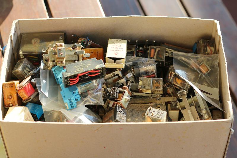
Not being a millennial, I do have some tools and spare parts. For VERY large values of “some”. This for example is my box of spare relays.

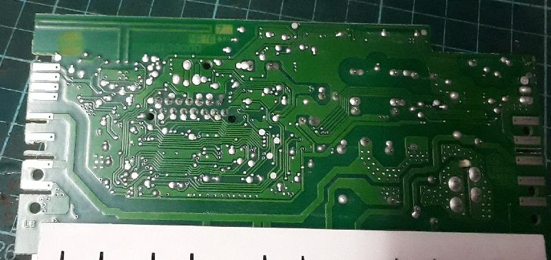
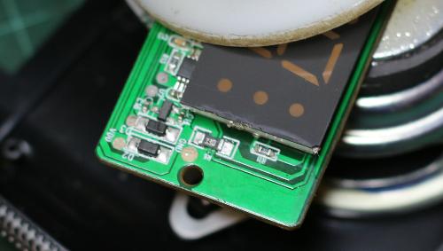
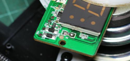
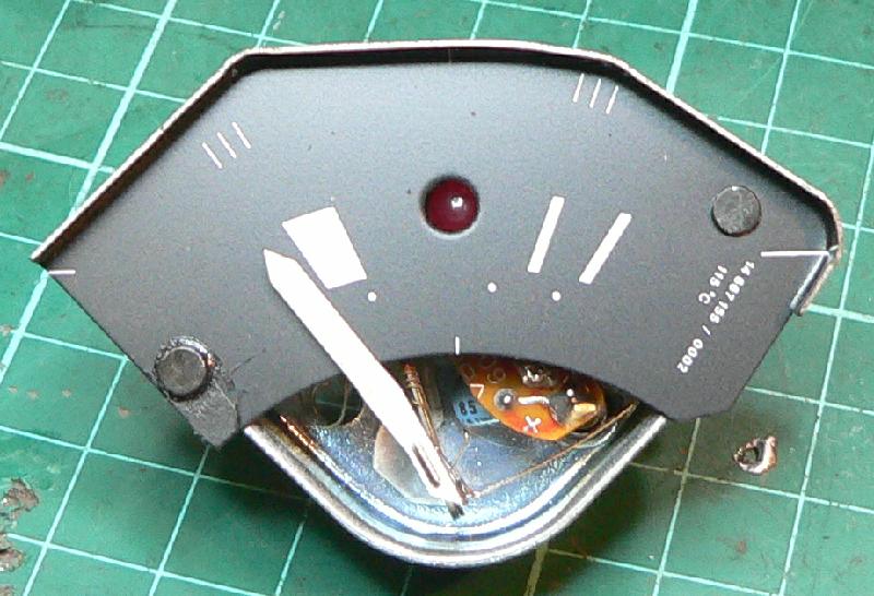
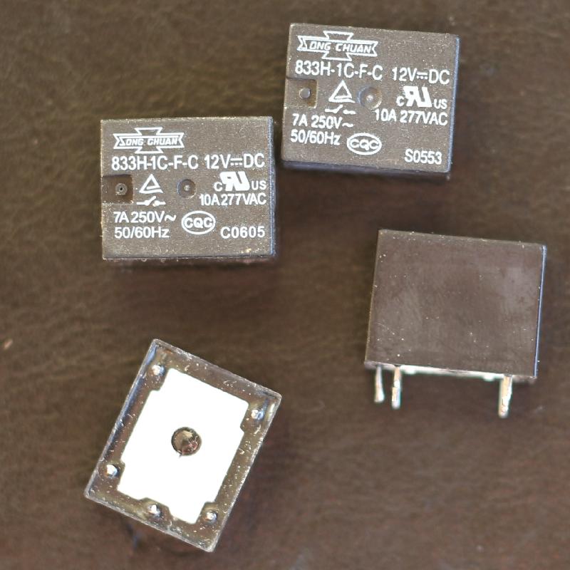
These ones look like just the thing.

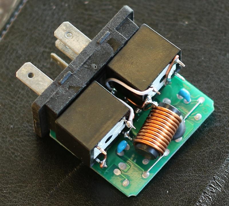
Yup, it works. Cover doesn’t fit back on again, but it will with some surgery if required. I am not too concerned.

The kid’s father is coming down from the UK in two weeks’ time and he’ll bring down the Real Thing but in the mean time this will do. Very Nicely. R1710. Fsck.


Clock Radio Hacking

Nice little clock radio with a docking station for charging a cellphone. I bought it through One Day Only or something.

One big problem, though. The display is so flippin’ bright that it keeps you awake at night. Draws moths, even. Not ideal.

The large PCB at the top holds the buttons. All the work is done by what one would have thought is the display board.

Clock, radio, everything. One would have thought they could have put an LDR in there to make the thing dim automatically when it gets dark. Philips is not what they used to be.

The 330 ohm resistor is not like the other resistors. Specifically, it’s a higher-wattage 0805 package and not 0603 like all the other resistors on the board*. Figuring that there must be a reason for this, this is where I started.

Replaced it with a 1k and sure ’nuff, the display is now bright enough to still read indoors in daytime, but dim enough to not outshine the street lights when we have them

* OK there are other 0805 resistors on the board. They bridge two or three traces, so I figured that’s why they chose bigger resistors in these positions. Also, 330 ohm is sort of the right value for an LED current limiter. Yea, it’s all gut feel. Sometimes it works.


When your failure detection system fails

The patient: A NAD T751 Surround-Sound amplifier.

The symptom: You turn it on, it thinks about it for about ten seconds and turns itself off.

The cause: Well, the gnomes over at NAD built in a whole bunch of self-test diagnostics into the microcontroller. If the output transistors draw too much current, or there’s DC on the speaker lines, or… anything else, really… the system shuts down. One would hope to think that it also emits an error code of some type somewhere, but if it does it’s not documented where I could find it.

So the first step is of course to check the output transistors. This… is a mission. But after taking the whole damn thing apart I came to the conclusion that the transistors were just dandy. Not the problem.

OK, a preliminary google indicates that the protection system is likely to be the cause. Dried out capacitors and the like. Looking at the schematic, the Load board is a likely culprit, so I replaced all the caps on there. No change.

A lot more googling got me this page, and Andrew’s comment two thirds of the way down is the solution. There’s a bodge factory modification on the AC3 board that looks like it checks that the AC power is present. If the capacitor (Andrew claims 2.2 uF, I had 3.3 uF fitted) is buggered, the bodge doesn’t work and the amp powers itself down.

New cap fitted and all is well. Now the question is whether I tell the customer that the T-751 can’t be fixed, and keep it… because damn it sounds good.

So I bought a Tesla hybrid

A red one.

It’s a Type 4159 AB “Pluto” made in Czechoslovakia in the early eighties. Basically a 12V DC set, with a built-in transformer to turn 220V mains into 12V DC. This makes it nice and heavy — fortunately Turkish Air gives you 40kg baggage allowance.

They also bounce the bags quite a bit. Even wrapped in bubbles and spare clothing it still took a bit of strain. Fortunately the picture tube neck didn’t snap.

The story: we were in Prague, and it was a Sunday, and I had heard that there were flea markets all over the place, and the closest open one seemed to be Žižkov. So I got a tram ticket and headed off there.

Not as big as I thought it would be. They did however seem to have a rather large selection of lawnmowers.

Anyway, found the TV and two Metra Blansko multimeters (a PU-120 and a PU-140) for 15 euros.

The good news: It powers up. The bad news: Can’t get a station. The good news: I have the User Manual and Technical Manual. The bad news: It’s not in English.

Reading mask PROMs

So I’m messing around with a Burroughs TD831 terminal which uses a 6800 processor, 8 kilobytes of DRAM and 16 kilobytes of mask PROM.

The PROMs are fairly typical of the era, in that the chip select lines are also programmable. So you program the first one in a bank of four to have two active low chip selects, the middle two ones to have an active low and an active high, as well as the reverse, and the fourth one to have two active high chip selects. That way you can run address lines into the chip selects and four PROMs act like one PROM four times the size, effectively.

How I figured this out: the PROMs have 24 pins, the largest 24 pin PROM is a 2732. Told my EXPRO that’s what they were, not much joy. Went down to 2716s, and that gave data out of one of each bank of four PROMs. I figured that this means the devices are similar to for example the 82S191. So it was time to write some code.

I was lazy and just told the code that the three potential chip select lines were address lines. This gave me a 16 kilobyte per PROM dump, three quarters of which is blank Looking at how the banks were located in the 16 kilobyte address space makes it look like pin 21 (A10 on the 82S191) is an active high Chip Select, while pin 20 is A10 and pins 19 and 18 are the programmable Chip Selects.

I suppose I can rewrite my code to map things that way, but I should be able to paste my dumps together into something that can be disassembled. If ever I am arsed to do that.

But if you are here on a quest to restore one of these things to life, I think I have given you everything you need in order to be enlightened.

Edit: You might notice that I did change the code and re-dump the ROMs in nice neat 2k binaries.

VW Microbus temperature gauge repair

On our recent Kgalagadi trip the water bottle burst because the water level ran low. And the little red light that’s supposed to tell me that the water level was low never came on.

So I took the instrument cluster apart to find the problem

P1150143r

Here’s the gauge on the bench. Apparently if the light stays on it’s the capacitor and you can replace that without taking things apart. In my case however…

P1150144r

I had to drill out the two rivits holding the face plate on.

P1150149r

Lots of electronics to multiplex the analogue temperature and the low water signal from the relay on one wire. The PCB hangs off the two pins, gauge on the right (also goes to the heating element that moves the needle) and earth at the top. The blue wire from the left carries power (regulated 10V).

P1150154r

Hmmm. I think I see the problem.

SWR Meter rebuild

From a bunch of stuff some other ham wanted to throw away, this ex-SWR meter.

Stripped

I have no idea why the Dreaded Previous Owner stripped it down to this state. The meter movement is fine, 950-ish mV over a 4k7 resistor gives FSD, so it’s a 200uA unit.

inside

The detector components are still in place, and it looks very similar to the Micronta 21-520A except that there’s only one meter. There’s also a little bobbin on the side for an antenna, presumably to make it into a Field-Strength Meter, but that’s a gimmick and won’t happen.

NewSwitches

The junkbox yielded two switches of the right type and size (one selects Power / SWR, and in SWR mode the other selects Forward / Reverse). There will also be a pot to set FSD in Forward mode after which the Reverse mode should give the SWR. Give or take. Don’t expect a lot from meters like this.

Fast forward a bit and we have

IMG_0070r

IMG_0068r

Don’t ask me what used to live in those two extra holes. This setup works for me, for the price of a few junkbox parts and some time.


This… is stupid

(IMO, of course. And Geek Alert)

MFJ-949E

This is the switch and tuner schematic for an MFJ-949E Versa Tuner II. Great little unit, with a built-in dummy load. It has a switch that selects the dummy load, then the three antenna connectors in pass-through mode, then the three antenna connectors through the matching network, and then the dummy load again… through the matching network.

Which means that if you want to tune into the dummy load, you have to use the setting all the way to the left, or you have to adjust the tuner to match the dummy load to the rig, using the switch setting on the right.

Now why would you need to match a 50 ohm dummy load to your rig? Insane. The dummy load switch setting on the right should connect straight to the dummy load, not via the tuner.

I have a soldering iron, I can fix it.

New life for your FT-290R

I mentioned previously that I figured out how to make a new display for an FT-x90R. My own rig is still in pieces ‘cos I’m not quite happy with the software yet (or actually, with my reverse engineering of the display protocol, but it’s the same thing in the end).

But Dave ZS5DF wanted his rig fixed so I fitted a new display, even though it doesn’t have the F key “P” priority display function in firmware yet.

P1130871r

Two filament bulbs, because the replacement display needs light from the right-hand side and the S meter is on the left-hand side.

P1130882r

Component cost is close to R500 which almost puts it in good-money-after-bad territory but I like these little radios.

School project

Younger kid had to build an electric motor for a school project. Having a garage full of stuff, it was no hassle to find everything required to build one.

motor

close

I made her wind the coil.

But the question is, how do kids complete (or even conceptualise) something like this if they don’t have a Wouter around the house?

goes